3NC/3NB/3NK
2-3-1
2-3 Operati on of the PWBs
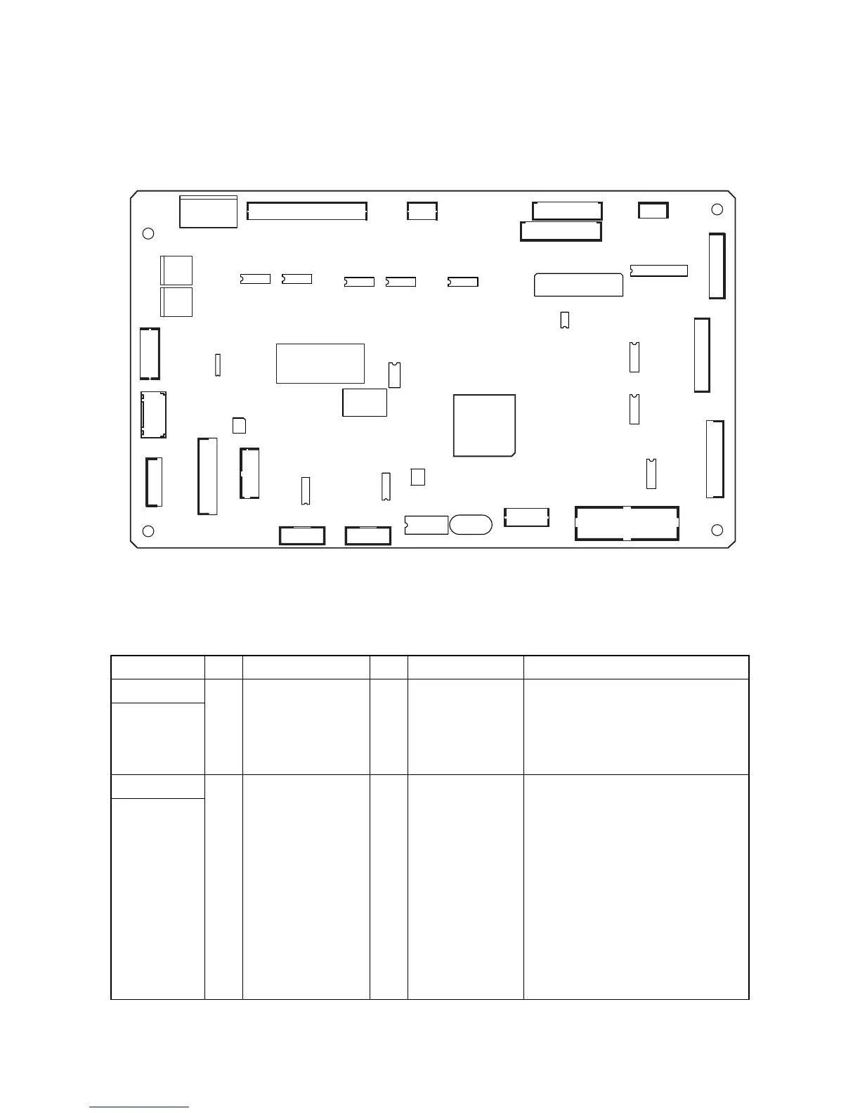
2-3-1 DF main PWB
Figure 2-3-1 DF main PWB silk-screen diagram
Connector Pin Signal I/O Voltage Description
YC3
1GND --
Ground
Connected to
machine
2GND --
Ground
3 24V1 I 24 V DC 24 V DC power input from Machine
4 24V1 I 24 V DC 24 V DC power input from Machine
YC6
1 24V1 O 24 V DC
24 V DC power outoput to DFFCSW
Connected to
the DF front
cover switch
and DF top
cover switch
2 FRONT COV SIG I 0/24 V DC
DFFCSW: On/Off
3TOP COV
SOURCE
O 0/24 V DC 24 V DC power output to DFTCSW
4 TOP COV SIG I 0/24 V DC DFTCSW: On/Off
YC11
YC5
YC1 YC2
YC20
YC10
YC17
YC12
YC13
YC14
YC6
YC16
YC15
YC18
YC8
YC3
YC19
YC4
YC9
U2 X1
U8
U3
U16
U17
U15
U19
U18
U9
U5
U6
U4
U7
U20
U1
U12U11U10
U14
U13
YC7
 Loading...