2LV/2L1/2L2/2MS/2MT
2-1-7
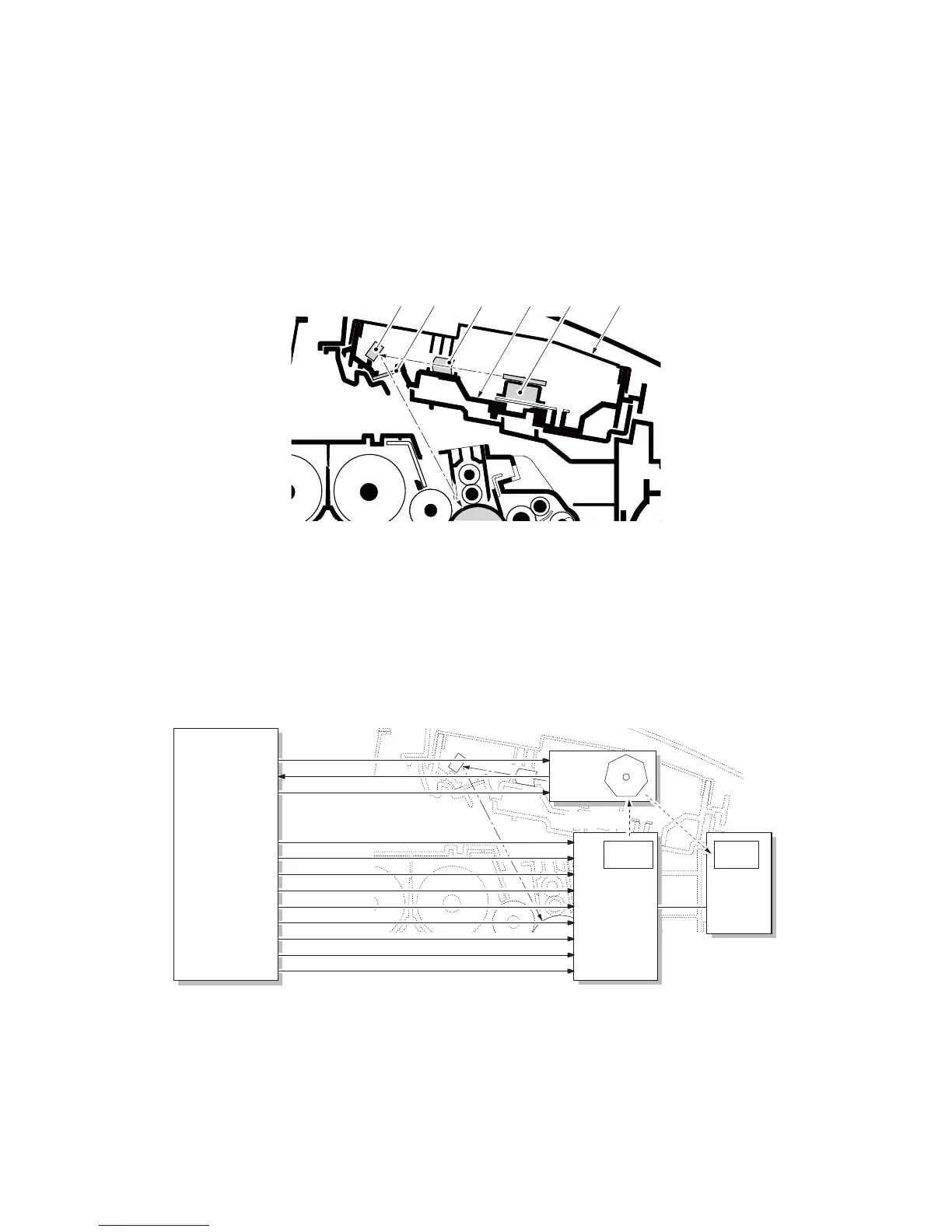
2-1-4 Optical section
(1) Laser scanner section
The charged surface of the drum is then scanned by the laser beam from the laser scanner unit. The laser
beam is dispersed as the polygon motor (PM) revolves to reflect the laser beam over the drum. Various lenses
and mirror are housed in the laser scanner unit, adjust the diameter of the laser beam, and focalize it at the
drum surface.
Figure 2-1-13 Laser scanner unit (LSU)
Figure 2-1-14 Laser scanner unit block diagram
123 4
5 6
1. Polygon motor (PM)
2. fθ main lens
3. Direction change mirrer
4. LSU dust shield glass
5. LSU base
6. LSU cover
YC15-3
YC15-4
YC15-5
YC16-2
YC16-3
YC16-4
YC16-5
YC16-7
PLGDRN
PLGRDYN
POLCLK
VDATA1P
VDATA1N
VDATA2P
VDATA2N
SAMPLEN2
YC16-6 YC2-2 PDPWB
SAMPLEN1 PDN
3
2 PM
1
APCPWB
EPWB
Photo
sensor
Laser
diode
Drum
Laser light
YC16-8
OUTPEN
YC16-9
VCONT1
YC16-10
VCONT2
 Loading...