Appendix Relay Module R16
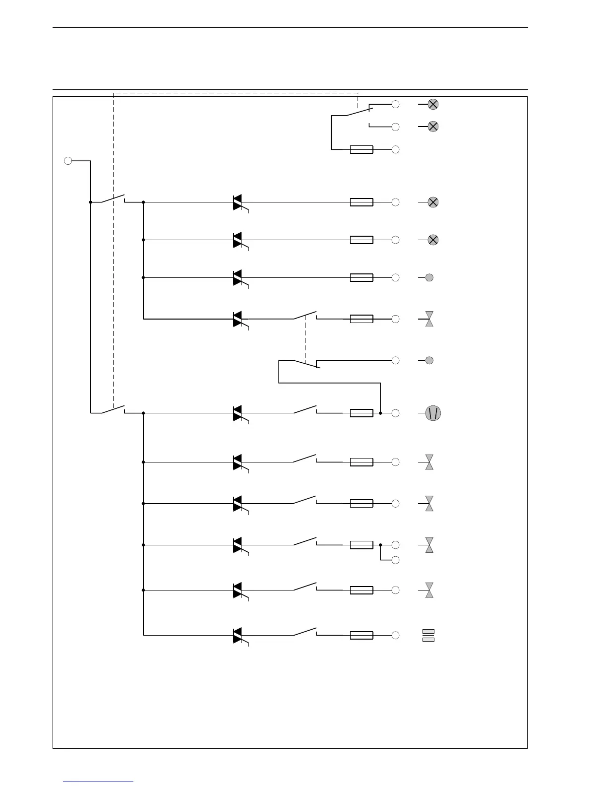
Contact plan, relay module type 6 60 R 0016 (since August 2006)
K10
L
Main gas 1
Ignition
transformer
Fan
(burner start)
Failure
Main gas 2
(burner side)
89
90
87
88
91
92
93
94
81
82
83
84
84
86
Oil valve
Gas operation
message
Oil operation
message
release external
ignition gas line
Pre-/post
ventilation
1A
0,5A
0,5A
2A
0,5A
0,5A
1A
2A
2A
2A
K9
K11
K9
K7
TC6
TC3
K3
K2
TC2
K1
TC1
F11
F10
F8
F6
F7
F9
F5
F3
F2
F1
Oil distribution
TC91
TC87
TC88
TC90
95
K6
Ignition valve
85
1A
K5
TC5
F4
K11
TC7
*)
*)
*)
*)
*)
*)
Operation
*) At terminals 82 through 86 an alternating testing current must flow. Otherwise the relais module will switch off
all outputs during the self-test which forces the FMS to do a fault-shutdown. At a mains voltage of 230V an
impedance of Z<=100kW is required. At 110V Z must be 22kW or less. If necessary connect an appropriate
auxiliary load (as a resistor or RC element). Outputs which are not switched on by the FMS (e.g. ignition valve
when starting without ignition burner) need no auxiliary load.
137

 Loading...

