42
FMS Commissioning Setting Control Elements
________________________________________________________
Aids
_________________________________________________________
_________________________________________________________
- “
Set "Lower stop”
Set the channel's target value to "0” via key (4)
- Red LED (B) comes on
- Actuator responds C1
- e.g. fan runs down or B1
- motor moves in the "CLOSED” direction E2
Limit switch to "CLOSED”. Adjust valve stop
Program the frequency converter to minimum rev. speed
Turn selector switch (1) to "Feedback actual value”
Adjust potentiometer to lower value
(see table below)
Set "Upper stop”
Turn selector switch (1) to "Target value”
Set target value = 999
Limit switch to "open” Adjust valve stop
Check frequency converter's maximum rev. speed
Turn selector switch to "Feedback actual value”
Check upper potentiometer value (see table)
Check rev. speed feedback value (see page 137)
Potentiometer adjustment values (approximate)
Pot Lower stop* Upper stop*
5kS 80 920
1kS 200 800
* assuming that full potentiometer rev. range is utilised
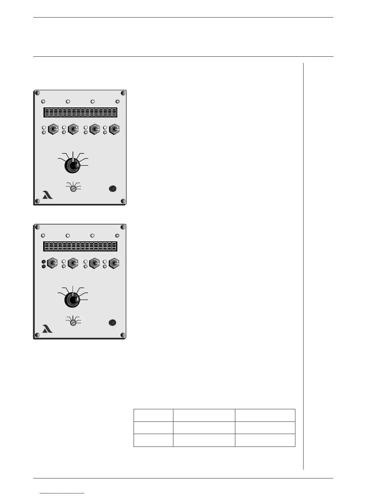
Operation of control elements
for potentiometer adjustment “Setting” mode permits direct access to the control
and limit switch settings elements. It is therefore essential to follow the safety rules
laid down by the burner manufacturer!
Adjust the control elements only when the system is at rest.
Selector switch (1) to "Actual value feedback”
Selector switch (2) to "Setting”
EI” appears on the display
LAMTECLAMTEC
xxx
xxx
xxx
xxx
2
1
CHANNEL 1 CHANNEL 2 CHANNEL 3 CHANNEL 4
LAMTECLAMTEC
xxx
xxx
xxx
xxx
A
B
ACTUAL VALUE
FEEDBACK
SETTING

 Loading...

