Status LEDs CoBox-Micro
2-4
Status LEDs
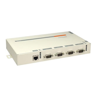
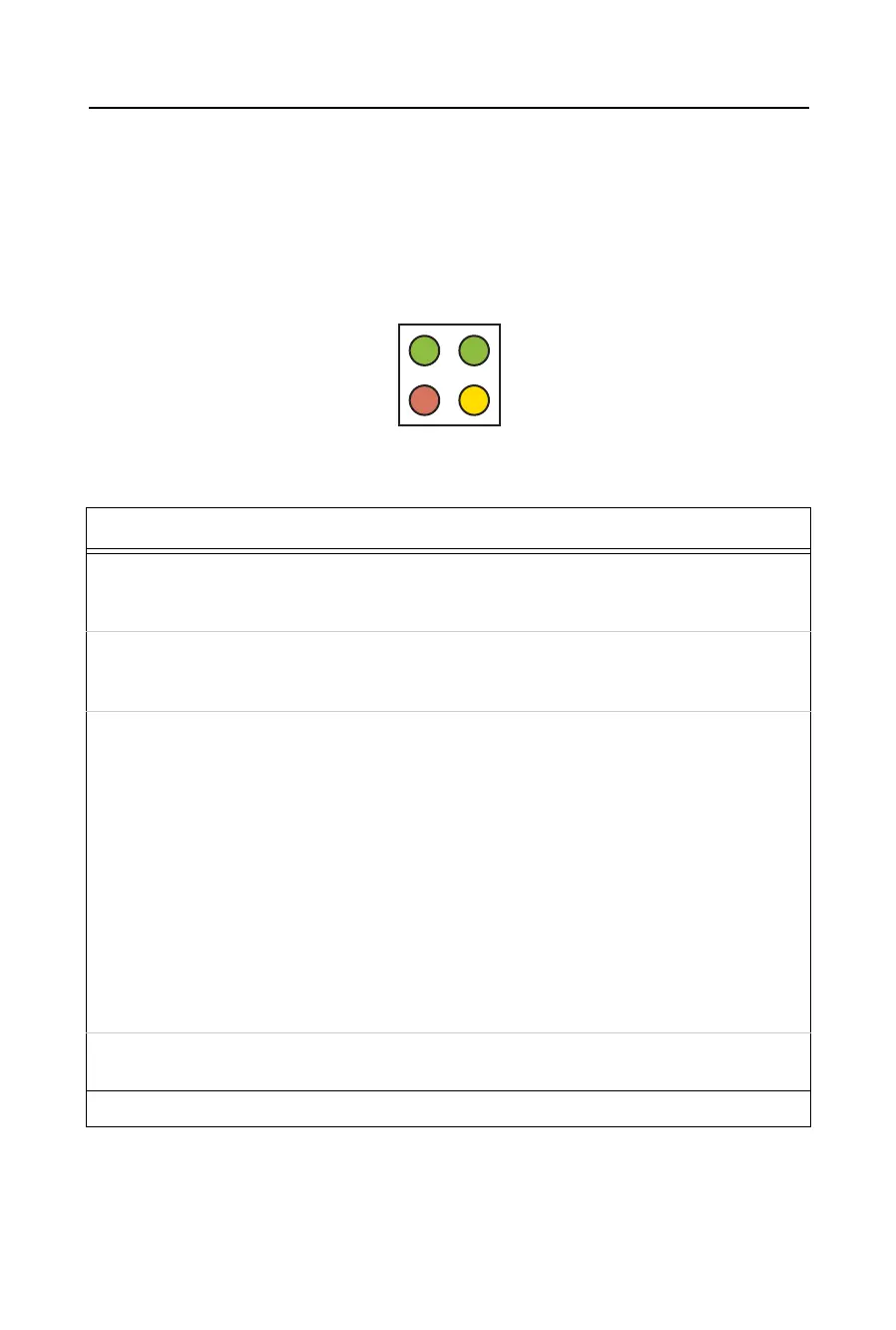
The CoBox-Micro has four status LEDs: serial port (Channel) 1 status, serial port
(Channel) 2 status, diagnostics, and network link status. See the following table for a
complete description of status LED pinout location and function.
Figure 2-4: CoBox-Micro Status LEDs
Table 2-2: CoBox-Micro Status LEDs
LED Description Location LED Functions
1SerialPort
(Channel) 1
Status
CON 4, Pin 4 Lights solid green to indicate Channel 1 is idle.
Blinks green to indicate Channel 1 is connected to the net-
work and active.
2SerialPort
(Channel) 2
Status
CON 4, Pin 7 Lights solid yellow to indicate Channel 2 is idle.
Blinks yellow to indicate Channel 2 is connected to the net-
work and active.
3 Diagnostics CON 4, Pin 3 Blinks or lights solid red in combination with the green
(Channel 1) LED to indicate diagnostics and error detection.
Red solid, green (Channel 1) blinking:
1x: EPROM checksum error
2x: RAM error
3x: Network controller error
4x: EEPROM checksum error
5x: Duplicated IP address on the network*
6x: Software does not match hardware*
Red blinking, green (Channel 1) blinking:
4x: Faulty network connection*
5x: No DHCP response received*
4Network
Link Status
CON 4, Pin 8 Lights solid green to indicate network port is connected to
the network.
*non-fatal error
1green
red
green
yellow
4
3
2
 Loading...