Integration Guidelines Test Environment
10-5
General Guidelines
This section covers the following topics:
! power supply
! network connector
! virtual ground
! serial signals
! emission improvements
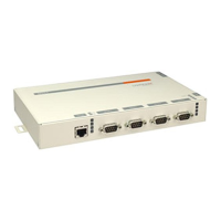
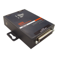
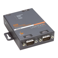
! CoBox-Mini
! CoBox-Mini100
! CoBox-Micro
Power Supply
The CoBox-Mini, CoBox-Mini100, and CoBox-Micro run at 5 VDC nominal, ±5%. The
current consumption varies for the different products and depends upon their operating
conditions. Refer to the current requirements listed in the product specification in order to
design an appropriate power supply.
To maintainthenecessary voltage,provide groundto the appropriate connector header with
a low inductance and low DC resistance path. The best solution is a solid ground plane.
Place a de-coupling capacitor pair as close as possible to the connector headers of the
board’s power supply. We recommend a ceramic (X7R material or equivalent, value
0,022uF to 0,1uF) and a low DC resistance (electrolytic or tantalum value 10uF to 100uF)
capacitor.
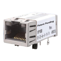
Network Connector
If you want to add an RJ45 connector, we recommend that it be at least partially shielded
in case it will be used in a noisy environment. (Please refer to the product specific section.)
450.01 37.69 46.00 -8.31
Table 10-3: CoBox-Mini100, cont.
Frequency
MHz
Field Strength
Level at 3 m
dBµV/m
Limit FCC
Class B
dBµV/m
DELTA
dB
Remarks
 Loading...