Do you have a question about the Lantronix CoBox-Micro and is the answer not in the manual?
Connectivity Technology | Wired |
---|---|
Ethernet Ports | 1 |
Power Supply | 5V DC |
Data Link Protocol | Ethernet |
Remote Management Protocol | SNMP, Telnet, HTTP |
Operating Temperature | 70°C |
Details the Lantronix Embedded Integration Kits and their contents for evaluating device servers.
Provides an overview of Lantronix embedded Device Servers and their primary applications.
Explains supported network protocols like TCP, UDP, ARP, etc., used by Device Servers.
Introduces the CoBox-Micro, its features, power needs, and supported protocols.
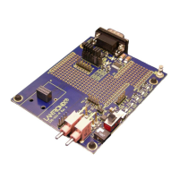
Presents a diagram and dimensions of the CoBox-Micro board for integration purposes.
Details the CoBox-Micro's TTL serial, RJ45, and LED connectors and their configurations.
Specific details about the RJ45 Ethernet connector on the CoBox-Micro and its options.
Describes the CoBox-Micro's status LEDs, their locations, and functions for diagnostics.
Information contained on the CoBox-Micro's product label, including barcode and MAC address.
Information about the CoBox-Micro test bed for development and testing applications.
Pinout details for the CoBox-Micro test bed connectors for easy reference.
Introduces the CoBox-Mini, its interface, power requirements, and supported protocols.
Presents a diagram and dimensions of the CoBox-Mini board for integration purposes.
Details the CoBox-Mini's TTL serial, AUI, UTP, and RJ45 connectors and their configurations.
Describes the CoBox-Mini's status LEDs, their locations, and functions for diagnostics.
Information contained on the CoBox-Mini's product label, including barcode and MAC address.
Information about the CoBox-Mini test bed for development and testing applications.
Pinout details for the CoBox-Mini test bed connectors for easy reference.
Introduces the CoBox-Mini100, its interface, power requirements, and supported protocols.
Presents a diagram and dimensions of the CoBox-Mini100 board for integration purposes.
Details the CoBox-Mini100's TTL serial and Ethernet connectors and their configurations.
Describes the CoBox-Mini100's status LEDs, their locations, and functions for diagnostics.
Information contained on the CoBox-Mini100's product label, including barcode and MAC address.
Information about the CoBox-Mini100 test bed for development and testing applications.
Pinout details for the CoBox-Mini100 test bed connectors for easy reference.
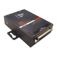
Introduces the UDS-10B, its serial interface, Ethernet, and supported protocols.
Presents a diagram of the UDS-10B board layout with key components.
Details the UDS-10B's female DB25 DCE serial port supporting RS-232 and RS-485 standards.
Details the UDS-10B's RJ45 Ethernet port and its power plug specifications.
Describes the UDS-10B's LEDs for Link, Network Tx/Rx, Collision, Diagnostics, and Status.
Information contained on the UDS-10B's product label, including barcode and MAC address.
Explains the default IP address (0.0.0.0) and how DHCP is automatically enabled.
Describes how AutoIP assigns addresses in networks lacking a DHCP server.
Outlines procedures for configuring the Device Server's IP address via network or serial port.
Covers changing the Device Server's DHCP name and its default naming convention.
Details steps to log into the Device Server via Telnet using ARP and port 9999.
Provides steps to log into the Device Server via its serial port using a terminal emulator.
Guide to configuring the Device Server via its internal web pages using a standard browser.
Steps for configuring the Device Server over the network using Telnet to port 9999.
Local configuration of the Device Server using a terminal emulator on the serial port.
Overview of parameters configurable in Setup Mode, including basic, security, and channel settings.
Configuration of basic server parameters like IP Address, Gateway, Subnet Mask, and passwords.
Configuration of channel-specific parameters like Baud Rate, Interface Mode, and Flow Control.
Defines how the Device Server establishes and reacts to network connections.
Options to control connection dropping behavior, including DTR drop and EOT.
Controls line handling and network buffers with connection startup and disconnect.
Settings for packing algorithms, idle time, trailing characters, and send characters.
Options to enhance security, including disabling Telnet/TFTP/Web setup, and password options.
Using the Lantronix Comm Port Redirector application to share serial devices via COM ports.
Steps to configure the Device Server for use with the Comm Port Redirector.
Discusses signal conditions, rise/fall times, and protection resistors for serial signals.
Describes the test setup, equipment, and UUT connection for emission testing.
Presents radiated emission test results for CoBox-Micro, CoBox-Mini, and CoBox-Mini100.
Provides guidelines on power supply, network connectors, virtual ground, and serial signals.
Information required when reporting a problem to Lantronix Technical Support.
Lists corporate and sales office contact details worldwide.
Provides phone numbers, email, and website for accessing technical support.
Introduction to Monitor Mode for diagnostic purposes and methods to enter it.
Lists available commands in Monitor Mode for querying and configuring the Device Server.
Information on where to find current firmware files and release notes.
Steps to download new firmware to the Device Server using a TFTP client.
Procedure for upgrading firmware on another Device Server over the network.
Steps to download firmware from a computer via the Device Server's serial port.
Provides dimensional data for the CoBox-Mini, Mini100, CoBox-Micro, and UDS-10B.
Lists common technical specifications for all four Device Servers.
How to configure or query the Device Server using UDP datagrams.
Creating and sending setup records in Intel Hex format for identical Device Server configuration.
Explanation of IP address structure, network portions, subnetting, and host identification.
Guide to converting binary values to hexadecimal representation for command assembly.
Diagram showing typical TTL-to-RS232 conversion circuits using DB-9 connectors.
Diagram showing typical TTL-to-RS232 conversion circuits using DB-25 connectors.
Details Lantronix's warranty for Device Servers and software, including procedures.