Page 13
TABLE 5
G26 BLOWER RATINGS 120V 1PH
BLOWER MOTOR HP
G26Q3
CAP
1/3
5MFD 370V
G26Q4/5
G26Q3/4
1/2
7.5MFD 370V
3/4 40MFD 370V
G26Q2
1/5
5MFD 370V
8-Combustion Air Blower (B6)
All G26 units use a combustion air blower to move air
through the burners and heat exchanger during heating opĆ
eration. The blower uses a PSC or shaded Pole 120VAC
motor. PSC motors use run capacitors. The motor operates
during all heating operation and is controlled by blower conĆ
trol A15. The blower operates continuously while there is a
call for heat. The ignition control is prevented from proceedĆ
ing through the ignition sequence until combustion air blower
operation is sensed by the prove switch.
The pressure switch connected to the combustion air blower
housing is used to prove combustion air blower operation.
The switch monitors air pressure in the blower housing. DurĆ
ing normal operation, the pressure in the housing is negaĆ
tive. If the pressure drops (becomes more positive), the
pressure switch opens. When the pressure switch opens,
the ignition control (A3) immediately closes the gas valve to
prevent burner operation.
9-Primary Limit Control (S10)
The primary limit (S10) on G26 units is located in the
middle of the heating vestibule panel. When excess heat
is sensed in the heat exchanger, the limit will open. If the
limit is tripped, the furnace control energizes the supply air
blower and de-energizes the gas valve. The limit automatiĆ
cally resets when unit temperature returns to normal. The
switch is factory set and cannot be adjusted. The switch
may have a different setpoint for each unit model numĆ
ber. However, the setpoint will be printed on the side of
the limit.
FIGURE 13
INSULATING COVER (s)
LIMIT CONTROL (S10) FOR
G26 SERIES UNITS AND ALTERNATE STYLE
SPADE CONNECTORS
LIMIT
Units may be equipped with either style limit.
10-Rollout Switch (S47) -3 Through -6
Flame rollout switch S47 is a SPST N.C. high temperature
limit located on the right side of the burner box assembly (see
figure 14). S47 is wired to the burner ignition control A3.
When S47 senses flame rollout (indicating a blockage
in the combustion passages), the flame rollout switch
trips, and the ignition control immediately closes the
gas valve.
Switch S47 in all G26 units is factory preset to open at
200F + 12F (93C + 6.7C) on a temperature rise. All
flame rollout switches are manually reset. A kit (#65K60) is
available for G26 -1 and -2 models.
FI
RE 14
FLAME ROLLOUT SWITCH (S47)
FLAME ROLLOUT
SWITCH (S47)
11- BCC2-3 Blower Control A15
(-1 and -2 models)
All G26-2 and -1 model units utilize the BCC2Ć3 blower conĆ
trol manufactured by Heatcraft. The BCC2Ć3 is a printed cirĆ
cuit board which controls the supply air blower and monitors
primary limit and gas valve operation. The control has a
nonĆadjustable, factory preset fanĆon" timing. Fan off" timĆ
ing is adjustable. The board is divided into two sections,
120 and 24VAC. Line voltage comes into the board on the
120VAC side. See figure 16.
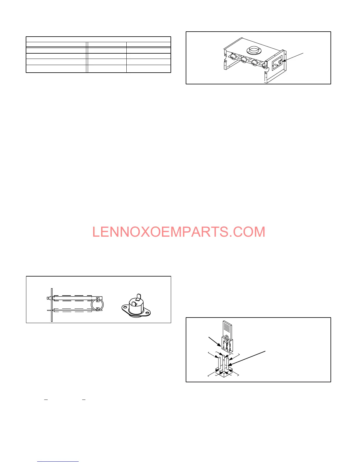
Fan Timings
Fan off" timing (time that the blower operates after the heat
demand has been satisfied) is determined by the arrangeĆ
ment of a jumper across pins on the BCC2Ć3 blower control
board. See figure 15. To adjust fan off " timing, gently disĆ
connect jumper and reposition across pins corresponding
with new timing. Fan on" time is factory set at 45 seconds
and is not adjustable.
NOTEĊIf fan off" time is set too low, residual heat in
heat exchanger may cause primary limit S10 to trip reĆ
sulting in frequent cycling of blower. If this occurs, adĆ
just blower to longer time setting.
Figure 15 shows the various fan off" timings and how jumper
should be positioned. Unit is shipped with a factory fan off"
setting of 90 seconds. Fan off" time will affect comfort and
efficiency and is adjustable to satisfy individual applications.
The fan off" timing is initiated after a heating demand but not
after a blower or cooling demand (that is, when indoor therĆ
mostat switch is changed from ON to AUTO and heating/
cooling demand is not present, the blower stops immediateĆ
ly).
FIGURE 15
FANĆOFF TIME ADJUSTMENT
270
210
150
90
To adjust fanĆoff timing:
Remove jumper from BCC2Ć3 and seĆ
lect one of the other pin combinations
to achieve the desired time.
TIMING
JUMPER
TIMING
PINS
(seconds)
Leave jumper off for
330 second fanĆoff timing.
 Loading...