Page 34
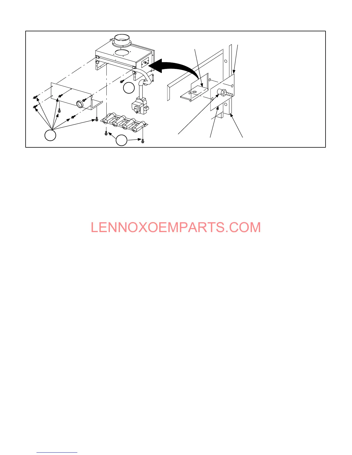
Simplified Burner Removal:
1- Remove cover by loosening
bottom screws (2) and reĆ
moving cover front screws
(5).
2- Remove pilot tube, spark
wire and sensor wire. ReĆ
move gas valve and manifold
assembly.
3- Remove burner assembly.
FIGURE 52
BURNER ACCESS/REMOVAL
2
3
1
PATCH PLATE
BARBED PRESSURE
SWITCH ORIFICE
BURNER MOUNTING
BRACKET
PATCH PLATE
UNIT VEST PANEL
30- ReĆinstall the burner box. Tighten the screws holding
the support bracket. It is important that the glass fiber
gasket not be damaged so it will provide a continuous
seal between the burner box and the vestibule panel.
31- With the pressure switch oriented on the right, reconĆ
nect pressure switch tubing by connecting the tubing
from the burner box to the barb on the bottom and the
tubing from the combustion air blower to the barb on
the top. See figure 23.
32- Reconnect the sensor and ignitor wires.
33- ReĆinstall top cap to unit.
34- ReĆinstall electrical connections to gas valve. Orange
wire to M1 and yellow wire to C2. Reconnect wires to
flame rollĆout switch.
NOTE - Unit is polarityĆsensitive. 120V supply wiring
must be installed correctly.
35- Reconnect main gas line to gas valve.
36- ReĆinstall field makeĆup box if removed.
37- ReĆinstall exhaust pipe/flue collar and secure flue colĆ
lar to the unit top cap using existing screw. Insert the
bottom of the flue collar into the top of the flue transiĆ
tion and tighten hose clamp.
38- ReĆinstall intake pipe fitting to burner box with screws.
39- Replace both upper and lower access panels.
40- Refer to instruction on verifying gas and electrical conĆ
nections when reĆestablishing supply.
41- Following lighting instructions from installation manuĆ
al, light and run unit for 5 minutes to ensure heat exĆ
changer is clean, dry and operating safely.
Cleaning the Burner Assembly
1 - Turn off electrical and gas power supplies to furnace.
Remove upper and lower furnace access panels.
2 - Disconnect the gas supply line to gas valve. DependĆ
ing on gas plumbing installation, the gas manifold
may move aside enough that breaking the union may
not be necessary.
3 - Remove five (5) screws from edges of burner box
cover. G26-50 units have only four (4) screws.
4 - Loosen two (2) screws on bottom of burner box front.
The cover is key holed at these screw point so screws
do not need to be removed. Pull off cover and set
aside.
6 - On -1 and -2 units disconnect pilot line at the gas
valve. On all units mark all gas valve wires and disĆ
connect them from valve.
7 - ON -1 and -2 units mark and disconnect spark and
sensor wire from the burner box at the ignition control.
On -3 mark and disconnect sensor wires from the
burner box at the SureLight control. Disconnect 2Ćpin
plug from the ignitor at the burner box.
8 - Loosen two (2) screws at the gas manifold support
bracket.
9 - Pull on the left side of the gas manifold and follow with
tension to the right side. The manifold support bracket
will be free of the mounting screws on the vestibule
panel. Set the gas manifold/gas valve assembly
aside. Take care not to damage foam gaskets on each
end of the gas manifold.
10- Using a 1/4" nut driver, remove the burner mounting
screws from underneath the burners.
 Loading...