Page 32
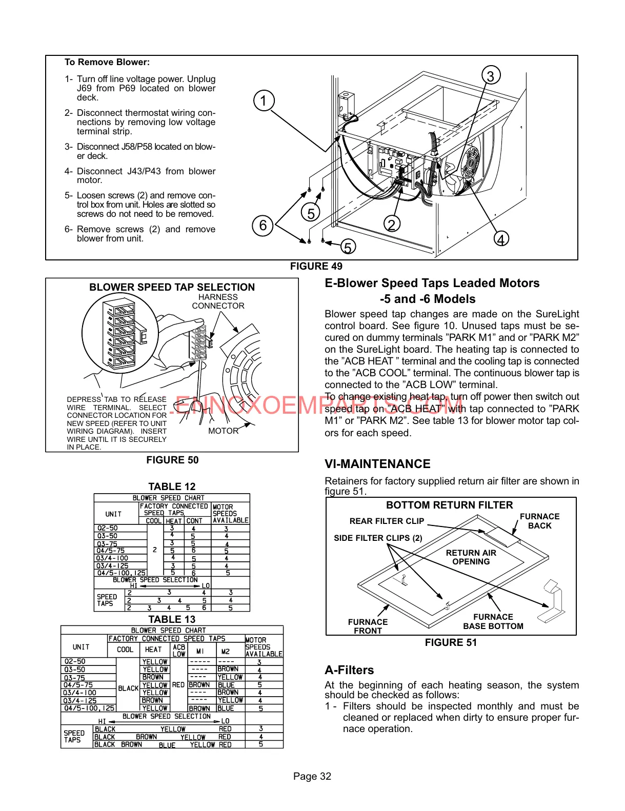
FIGURE 49
To Remove Blower:
1- Turn off line voltage power. Unplug
J69 from P69 located on blower
deck.
2- Disconnect thermostat wiring conĆ
nections by removing low voltage
terminal strip.
3- Disconnect J58/P58 located on blowĆ
er deck.
4- Disconnect J43/P43 from blower
motor.
5- Loosen screws (2) and remove conĆ
trol box from unit. Holes are slotted so
screws do not need to be removed.
6- Remove screws (2) and remove
blower from unit.
4
5
26
3
1
5
FIGURE 50
BLOWER SPEED TAP SELECTION
HARNESS
CONNECTOR
MOTOR
DEPRESS TAB TO RELEASE
WIRE TERMINAL. SELECT
CONNECTOR LOCATION FOR
NEW SPEED (REFER TO UNIT
WIRING DIAGRAM). INSERT
WIRE UNTIL IT IS SECURELY
IN PLACE.
TABLE 12
TABLE 13
E-Blower Speed Taps Leaded Motors
-5 and -6 Models
Blower speed tap changes are made on the SureLight
control board. See figure 10. Unused taps must be seĆ
cured on dummy terminals "PARK M1" and or "PARK M2"
on the SureLight board. The heating tap is connected to
the "ACB HEAT " terminal and the cooling tap is connected
to the "ACB COOL" terminal. The continuous blower tap is
connected to the "ACB LOW" terminal.
To change existing heat tap, turn off power then switch out
speed tap on "ACB HEAT" with tap connected to "PARK
M1" or "PARK M2". See table 13 for blower motor tap colĆ
ors for each speed.
VI-MAINTENANCE
Retainers for factory supplied return air filter are shown in
figure 51.
FIGURE 51
BOTTOM RETURN FILTER
FURNACE
BASE BOTTOM
REAR FILTER CLIP
RETURN AIR
OPENING
SIDE FILTER CLIPS (2)
FURNACE
FRONT
FURNACE
BACK
A-Filters
At the beginning of each heating season, the system
should be checked as follows:
1 - Filters should be inspected monthly and must be
cleaned or replaced when dirty to ensure proper furĆ
nace operation.
 Loading...