Page 28
12- If the furnace will not operate, follow the instructions
To Turn Off Gas To Unit" and call your service techniĆ
cian or gas supplier.
To Turn Off Gas To Unit
1 - Set thermostat to lowest setting.
2 - Turn off all electrical power to unit if service is to be
performed.
3 - Remove heat section access panel.
4 - On Honeywell VR8204 gas valves, turn knob on gas
valve clockwise to OFF. For White Rodgers 36E
gas valves, move switch to OFF. Do not force.
5 - Replace unit access panel.
C-Safety or Emergency Shutdown
Turn off unit power. Close manual and main gas valves.
D-Extended Period Shutdown
Turn off thermostat or set to UNOCCUPIED" mode. Close
all gas valves (both internal and external to unit) to guaranĆ
tee no gas leak into combustion chamber. Turn off power
to unit. All access panels, covers and vent caps must be in
place and secured.
Refer to Maintenance" section of this manual for instrucĆ
tions on how to prepare condensate assembly for exĆ
tended period shutdown.
IV-HEATING SYSTEM SERVICE CHECKS
A-A.G.A./C.G.A. Certification
All units are A.G.A. and C.G.A. design certified without
modifications. Refer to the G26 Operation and Installation
Instruction Manual Information.
B-Exhaust CO
2
and CO content
Carbon Dioxide is a colorless and odorless gas produced
in small amounts by all furnaces, including the G26, during
combustion process. When the unit is properly installed
and operating normally, the CO
2
content of the exhaust is
between 6.0% and 8.0% for natural gas and between
7.5% and 9.5% for L.P. gases. CO content will be less than
0.04% regardless of the gas used. If unit appears to be opĆ
erating normally at or beyond the upper limit of the CO
2
range, the unit should be checked for abnormally high CO.
Testing for abnormally high CO
2
and CO.
One method for testing the CO
2
/CO content is the BacharĆ
ach CO
2
test with the Fyrite CO
2
indicator. Other methods
of testing CO
2
/CO are available. Closely follow the instrucĆ
tions included in the test kit you choose. Follow the proceĆ
dure below in order to check CO
2
/CO on the G26 furnace.
1 - Drill size "R" or 11/32 in. on the exhaust vent, just exitĆ
ing the cabinet and tap 1/8-27 NPT. This hole will be
used to draw your CO
2
/CO sample.
2 - Install a hose barb connector into test hole.
3 - Attach end of Fyrite sampling tube to hose barb.
4 - Set thermostat to highest setting and allow unit to run
15 minutes.
5 - When CO
2
/CO testing is complete, turn off unit, reĆ
move hose barb from exhaust vent and use a1/8"
plastic plug to close off port.
C-Gas Piping
Gas supply piping should not allow more than 0.5"W.C.
drop in pressure between gas meter and unit. Supply gas
pipe must not be smaller than unit gas connection. See gas
pipe capacity table on page 6 of this manual.
Compounds used on gas piping threaded joints should be
resistant to action of liquefied petroleum gas.
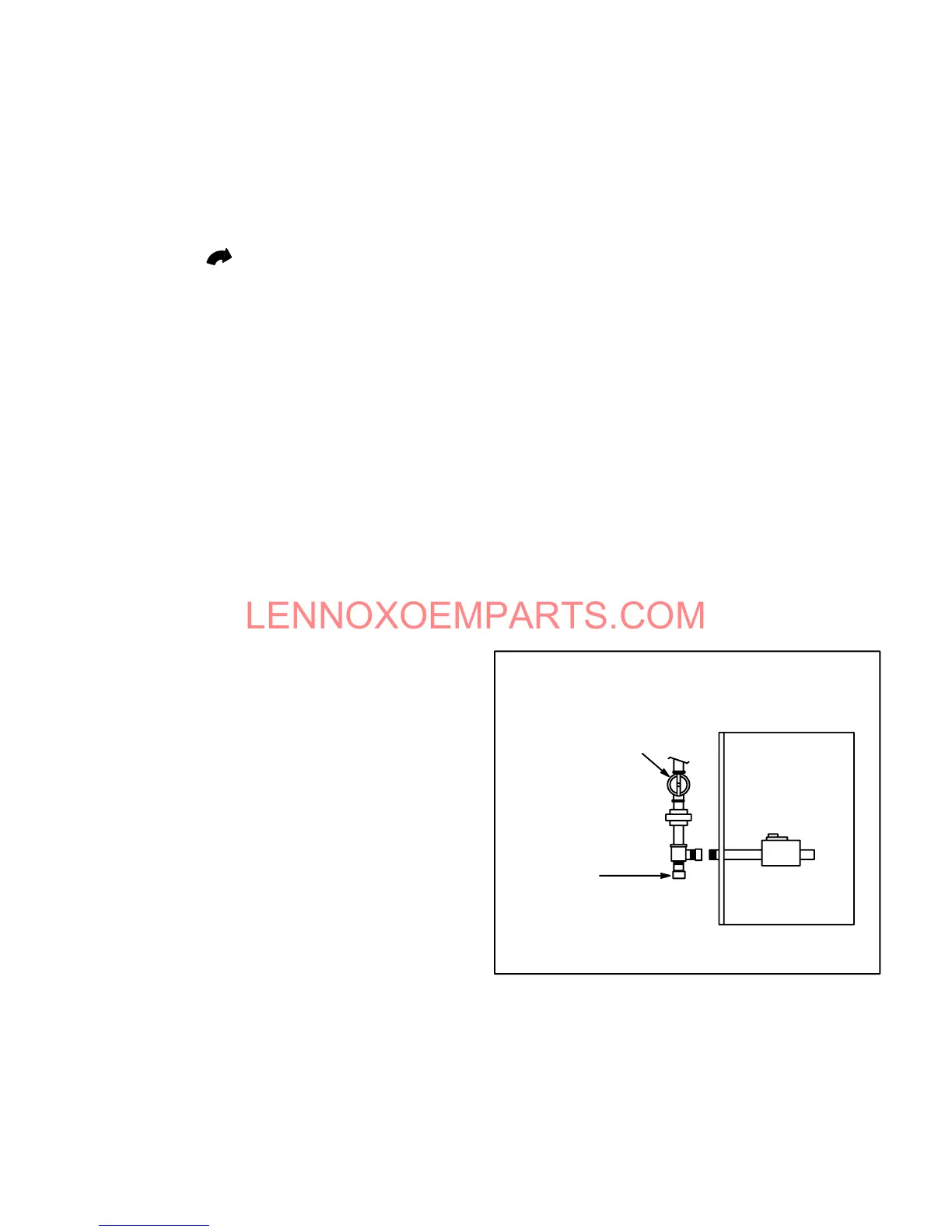
D-Testing Gas Piping
When pressure testing gas lines, the gas valve must be
disconnected and isolated. Gas valves can be damaged if
subjected to more than 0.5psig (14" W.C.). See figure 44. If
the pressure is equal to or less than 0.5psig (14"W.C.), use
the manual shut-off valve before pressure testing to isoĆ
late furnace from gas supply.
FIGURE 44
GAS VALVE WILL NOT HOLD TEST PRESSURE IN
EXCESS OF 0.5 PSIG (14"W.C.)
MANUAL MAIN SHUT-OFF
VALVE WILL NOT HOLD
NORMAL TEST PRESSURE
CAP
FURNACE
ISOLATE
GAS VALVE
GAS PIPING TEST PROCEDURE (TYPICAL)
 Loading...