Page 14
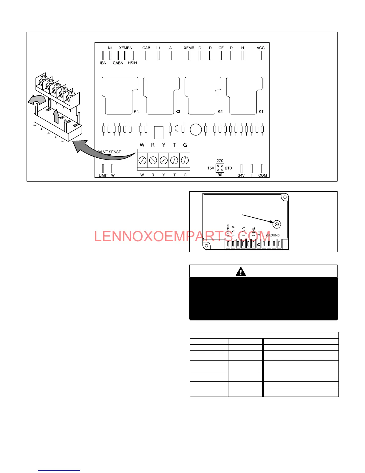
G26 BLOWER CONTROL Ć BCC2Ć3 (A15)
FIGURE 16
Table 8 shows
terminal designations.
Table 8 shows
terminal designations.
DETACHABLE
STRIP ON EARLY
BOARDS ONLY
12-Ignition Control (-1 and -2 models)
G26 -1 and -2 model units use an intermittent pilot ignition
manufactured by Johnson Controls. The ignition control is
located on the upper vest panel.
Unit Operation
When there is a call for heat, the control is prevented from
beginning an ignition sequence until the pressure switch
proves combustion air blower operation. When the pressure
switch closes, the control generates a spark and opens the
pilot valve to ignite the pilot. When flame is sensed, the conĆ
trol opens the main gas valve and the pilot ignites the main
burners. The indoor blower starts after a 45 second delay.
Gas valve remains open and combustion air blower continĆ
ues to run until demand stops, flame sensor senses loss of
flame, a limit opens or the prove switch opens. If any of these
events occur during a thermostat demand, the gas valve
closes.
The control will attempt ignition for 85 seconds. If ignition is
not successful, the control will lockout (indicated by flashĆ
ing LED). Within one hour the control will momentarily reĆ
move then reapply the thermostat signal and the ignition
sequence will begin again (Watchguard circuit). If pilot
ignition is successful, but flame is lost when the main valve
opens, the ignition sequence will retry up to 15 more times.
If ignition is not successful after the 16th try, the control will
shutĆdown and must be reset manually. Manual reset is
accomplished by removing thermostat demand for at least
2 seconds then reapplying demand.
FIGURE 17
IGNITION CONTROL A3
SPARK
OUTPUT
SEE TABLE 6
FOR TERMINAL
DESIGNATIONS
DANGER
Shock hazard. Spark related components contain
high voltage. Disconnect power before servicing.
Control is not field repairable. If control is inoperĆ
able, simply replace entire control.
Can cause injury or death. Unsafe operation will
result if repair is attempted.
TABLE 6
IGNITION CONTROL A3 TERMINAL DESIGNATIONS
Terminal Type Function
GROUND 1/4" Spade Cabinet Ground
THS 2 1/4" Spade
Safety Limit 24VAC Input
From Differential Switch
P. V. 1 1/4" Spade
24VAC Output to Pilot Operator
of Gas Valve
M.V.3 1/4" Spade
24VAC Output to Main Operator
of Gas Valve
SENSE 4 1/4" Spade Microamp Flame Sensing Input
Unmarked
Pin Type
Bare Wire
High Voltage Spark Output
 Loading...