Page 30
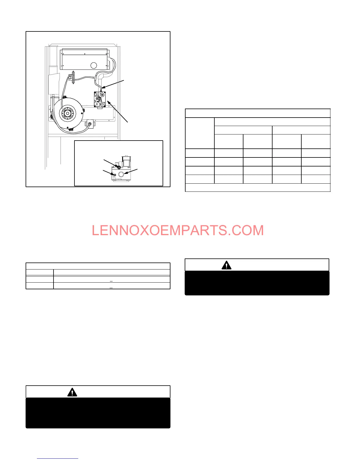
FIGURE 46
MANIFOLD CHECK
GAS
VALVE
SENSING
HOSE
GAS
VALVE
TOP VIEW GAS VALVE DETAIL
OUTLET
PRESSURE
TAP
HOSE
BARG
GAS
PIPING
4 - While waiting for the unit to stabilize, notice the flame.
Flame should be stable and should not lift from burner.
Natural gas should burn blue. L.P. gas should burn
mostly blue with some orange streaks.
5 - After allowing unit to stabilize for 5 minutes, record
manifold pressure and compare to values given in
table 9. Regulator cap must be installed when reading
pressures.
Absolute Pressure (outlet) in. W.C.
TABLE 9
GAS VALVE REGULATION*
3.5 +0.3
Natural
L.P.
7.5 +0.7
Unit (Fuel)
NOTE-Shut unit off and remove manometer as soon as
an accurate reading has been obtained. Take care to
replace pressure tap plug.
NOTE-During this test procedure, the unit will be
overfiring:
Operate unit only long enough to obtain accurate readĆ
ing to prevent overheating heat exchanger.
Attempts to clock gas valve during this procedure
will be inaccurate. Measure gas flow rate only during
normal unit operation.
6 - When test is complete remove obstruction from hose
and return hose to gas valve barb.
WARNING
Fire and explosion hazard.
These instructions MUST be followed exactly.
Can cause a fire or explosion resulting in property
damage, personal injury or loss of life.
G- Proper Gas Flow (Approximate)
Furnace should operate at least 5 minutes before checkĆ
ing gas flow. Determine time in seconds for two revoluĆ
tions of gas through the meter. (Two revolutions assures
a more accurate time.) Divide by two and compare to time
in table 10 below. Adjust manifold pressure on gas valve
to match time needed.
NOTE- To obtain accurate reading, shut off all other
gas appliances connected to meter.
TABLE 10
GAS METER CLOCKING CHART
Seconds for One Revolution
Natural LP
1 cu ft
Dial
2 cu ft
Dial
1 cu ft
Dial
2 cu ft
DIAL
-50 72 144 180 360
-75 48 96 120 240
-100 36 72 90 180
-125 29 58 72 144
Natural-1000 btu/cu ft LP-2500 btu/cu ft
H-High Altitude Derate
Units are selfĆcompensating for altitude and do not require
kits or adjustment when installed below 7500 ft. elevation.
Manifold pressure should remain the same for both natural
and propane. If unit is installed at an altitude higher than
7500 feet (2248 m), refer to local codes.
NOTE-This is the only permissible field derate for this
appliance.
IMPORTANT
For safety, shut unit off and remove manometer as
soon as an accurate reading has been obtained.
Take care to replace pressure tap plug.
I-Flame Signal
A 20 microamp DC meter is needed to check the flame sigĆ
nal on the SureLight and Johnson G776 ignition control. Use
a flame signal transducer (part number 78H5401) available
from Lennox to measure the flame signal.
Flame (microamp) signal is an electrical current which
passes from the ignition control through the sensor elecĆ
trode during unit operation. Current passes from the senĆ
sor through the flame to ground to complete a safety cirĆ
cuit.
To Measure Flame Signal:
1 - Set the volt meter to the DC voltage scale. Insert transĆ
ducer into the VDC and common inputs. Observe corĆ
rect polarities. Failure to do so results in negative (-)
values.
2 - Turn off supply voltage to control.
3 - Disconnect flame sensor lead from terminal of ignition
control.
 Loading...