34
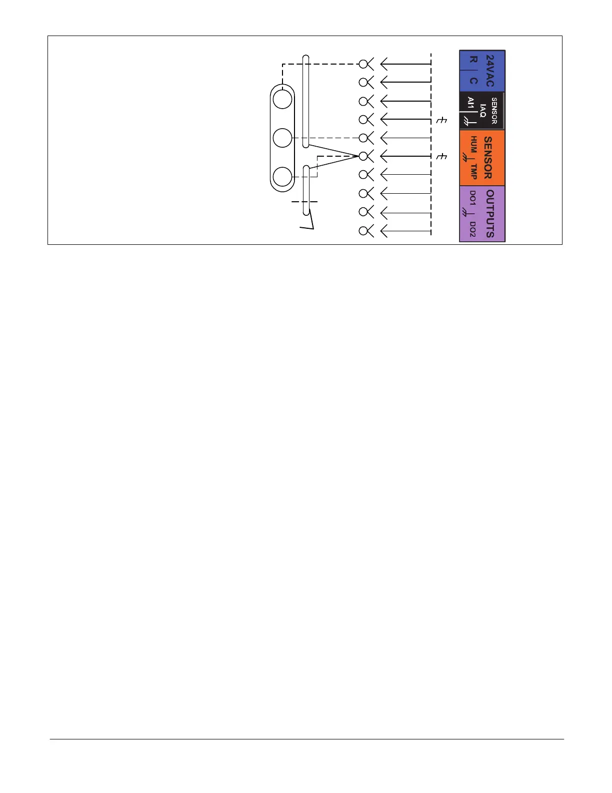
A91 HUMIDITY SENSOR
0 - 10VDC = 0-100%
relative humidity
Two separate shielded cables required.
One wire of the two
pairs is not connected.
P298
J298A
1
2
B
3
4
C
5
6
7
D
8
9
10
A91
VIN
VO
GND
R
C
AI-1
HUM
TMP
DO-1
C
DO-2
Figure 6. Relative Humidity Sensor Diagram
Go to SETTINGS > RTU OPTION > EDIT PARAMETER = 106 (DEHUMID SETPOINT) and 107 (DEHUMID
DEADBAND) (see paragraph 6.3. for further details concerning dehumidification set point)
Parameter 105 (Option 3) - Humiditrol
®
Reheat
Additional conditions to activate Humiditrol
®
Reheat:
Blower energized.
Occupied time period.
One previous cooling demand must have occurred.
Parameter 105 (Option 4) - Relative Humidity Measurement
When an optional relative humidity sensor is installed, the relative humidity percentage can be displayed on the M3 unit
controller and over the L Connection network via the network control panel or computer software client.
Option 4 is NOT used to control Humiditrol
®
or Supermarket Reheat. Refer to figure 37 - RH sensor wiring.
Parameter 105 (Option 5) - Humiditrol
®
Reheat
Condition is at least one previous cooling demand.
Parameter 105 (Option 6) - Humiditrol
®
Reheat
Additional conditions to activate Humiditrol
®
Reheat:
Blower energized.
Occupied time period.
Parameter 105 (Option 7) - Humiditrol
®
Reheat
Humiditrol
®
reheat with no additional conditions.

 Loading...