Electrical installation
Relay output connection
5
103
EDK82MV371 DE/EN/FR 7.0
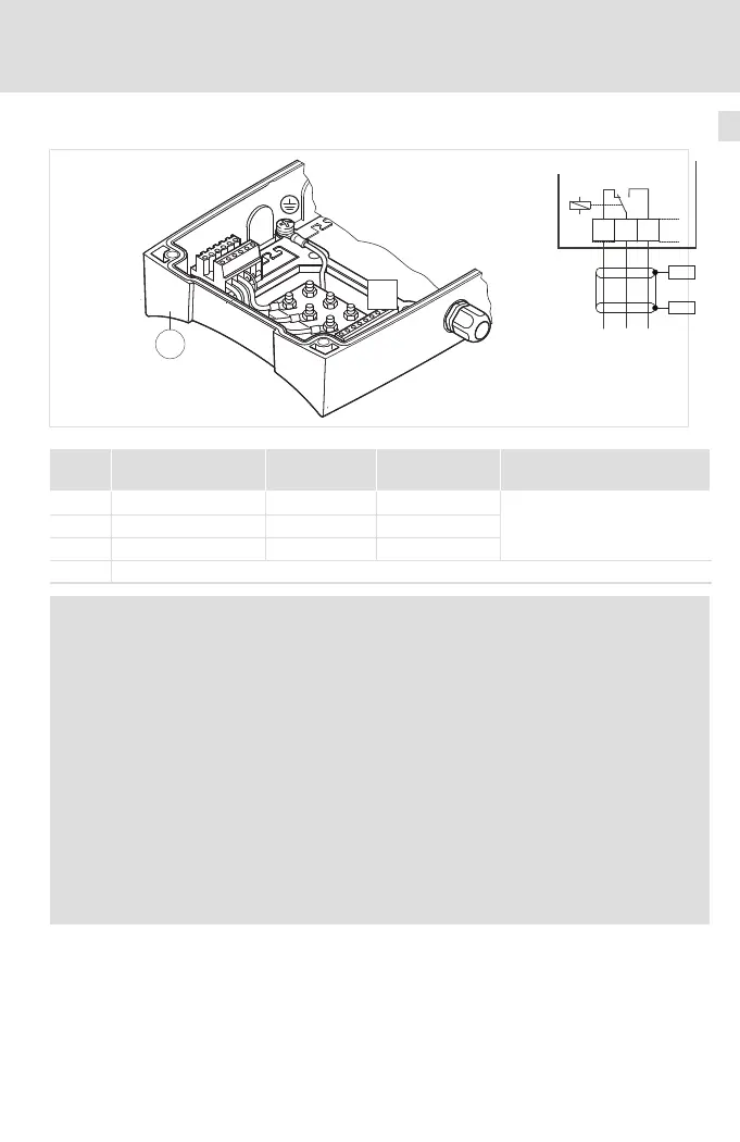
Relay output connection
Fig. 5−1
X1
PES
PES
1a
8200 motec
K11 K12 K14X1
8200mot058
Function Relay position
Message
(Lenze setting)
Technical data
X1/K11 NC contact Open TRIP
AC 250 V/3 A
DC 24 V/2 A ... DC 240 V/0.22 A
X1/K12 Centre contact
X1/K14 NO contact Closed TRIP
PES HF−shield termination by large surface connection to PE
Note!
ƒ Switching of control signals:
– Use shielded cables
– HF−shield termination by PE connection
– The minimum load for switching the signals through correctly is 12 V
and 5 mA. Both values have to be exceeded at the same time.
ƒ Switching of mains potentials:
– Unshielded cables are sufficient
ƒ For the protection of the relay contacts a corresponding suppressor circuit
is absolutely required for an inductive or a capacitive load!
ƒ The service life of the relay depends on the type of load (ohmic, inductive
or capacitive) and the value of the switching capacity.
ƒ The message that is output can be changed in code C0008 or C0415/1.
 Loading...