Commissioning
Vector control
7
113
EDK82MV371 DE/EN/FR 7.0
Vector control
The following instructions apply to controllers equipped with a standard−I/O function
module and a three−phase AC motor which has been selected according to a power−based
assignment.
Switch−on sequence Comment
1. Connect keypad
2. Ensure that controller inhibit is active after mains
connection
Terminal X3/28 = LOW
3. Switch on the mains
4.
5.
The keypad is in "Disp" mode after approx. 2 s and
indicates the output frequency (C0050)
The USEr menu is active
6. Go to the ALL menu
7. Change to the mode to configure the basic
settings for your drive
Blinking on the display: 0050
8. Adapt the terminal configuration to the wiring
(C0007)
Lenze setting: −0−, i. e.
E1: JOG1/3 fixed setpointselection
E2: JOG2/3
E3: DCB DC brake
E4: CW/CCW rotation
9. Set the minimum output frequency (C0010)
Lenze setting: 0.00 Hz
10. Set the maximum output frequency (C0011)
Lenze setting: 50.00 Hz
11. Set the acceleration time T
ir
(C0012)
Lenze setting: 5.00 s
12. Set the deceleration time T
if
(C0013)
Lenze setting: 5.00 s
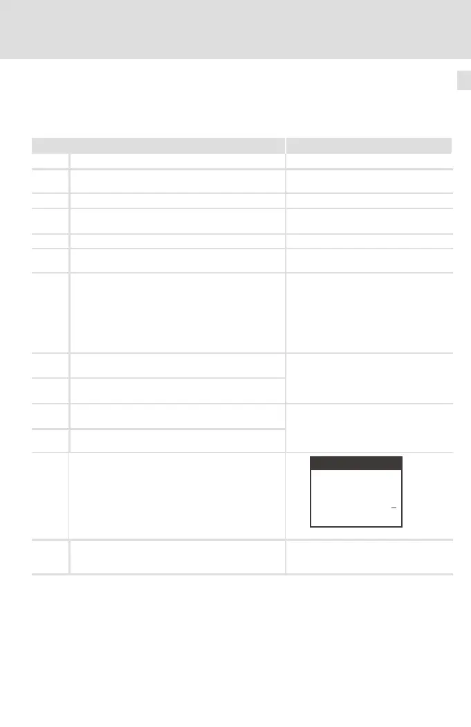
13. Activate the control mode "vector control" (C0014 =
4)
Lenze setting: Linear V/f characteristic control
(C0014 = 2)
d ABbc
p
SHPRG
Para
Code
Menu
0014
00
4
Vector-Ctrl
9371BC008
14. Adapt the voltage/current range for the analog
setpoint selection (C0034)
Lenze setting: −0−, (0 ... 5 V/0 ... 10 V/0 ... 20 mA)
Set the DIP switch on the standard I/O
to the same range (see Mounting
Instructions for the standard I/O)
 Loading...