Operation
Communicating via the CAN gateway function
Establishing communication using the Drive PLC Developer Studio (DDS)
8
78
LDCDS−EL100 EN 8.0
8.5.5 Establishing communication using the Drive PLC Developer Studio (DDS)
The used bus system must be selected for the communication via the EL100
communication module. System bus−specific settings can be made on the EL100 module
in the "CAN Gateway" applet. The communication module can only be selected via the
system bus configurator.
Commissioning is illustrated by the following example. The parameter data of an 8400
frequency inverter are to be displayed using the Engineer.
How to proceed:
1. Start the Drive PLC Developer Studio (DDS) program and open the project to be
transferred via the EL100 communication module.
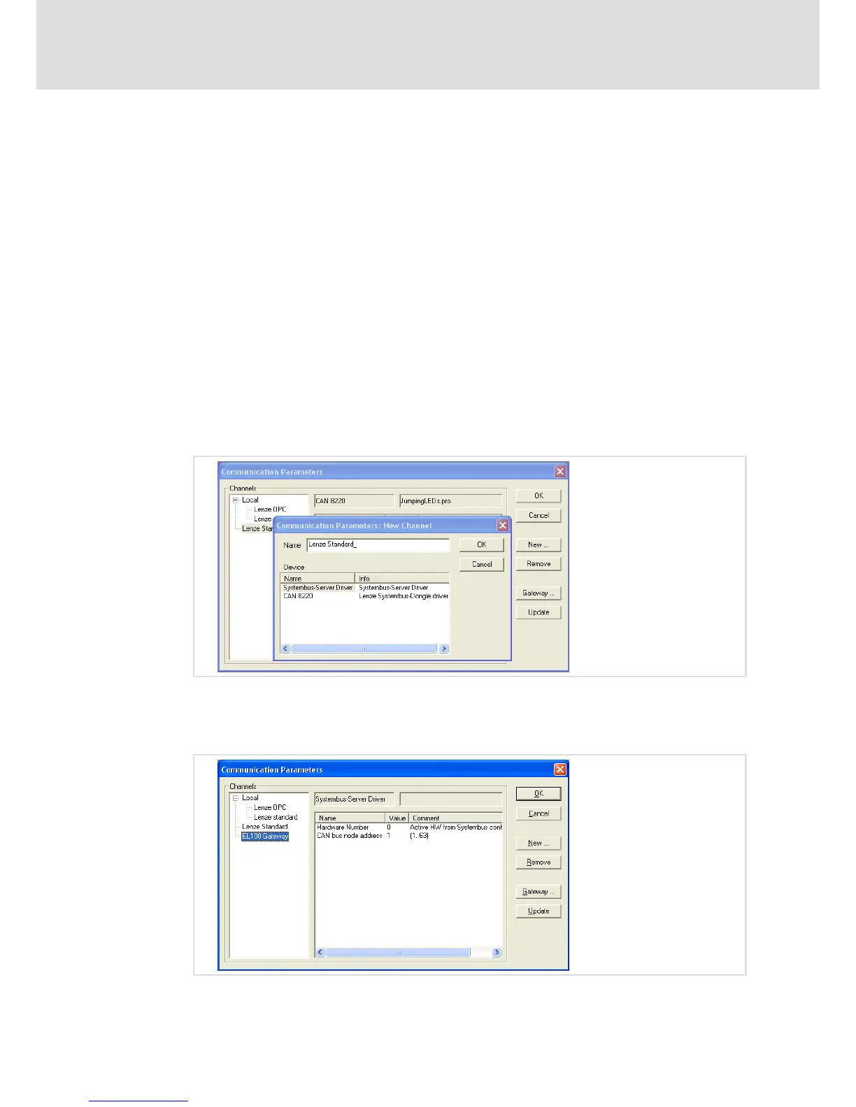
2. Activate the Online ® Communication parameters menu item.
The "Communication parameters" window is displayed. Here, the settings regarding
communication via the EL100 module can be made.
3. Click New to set a new channel.
4. Select the "Systembus Server Driver" for the EL100 communication module.
5. Assign an arbitrary name to the channel (e.g. EL100 Gateway).
6. Click OK.
A new channel is created.
 Loading...