4 Electrical installation
Wiring
EDKMF2133 DE/EN/FR 4.0
48
H2_Verdrahtung-TN anzahl
Wiring
ƒ Only use cables which correspond to the listed specifications, see (48).
ƒ Provide connection to the controllers by means of the bus connector. The bus system
will not be interrupted if the bus connector is removed from the controller.
ƒ Observe the notes and wiring regulations given in the documentation for the control
system.
ƒ Adapt baud rate to the bus cable length.
ƒ Check bus terminating resistors and activate them if necessary.
Specification of the transmission cable
Please follow the specifications of the PROFIBUS user organisation (PUO) for signal cables:
Bus cable specification
Specific resistance
135 - 165
Ω
/km,(f=3-20MHz)
Capacitance per unit length
≤
30 nF/km
Loop resistance
<110
Ω
/km
Core diameter >0.64mm
Core cross-section >0.34mm
2
Cores Double twisted, insulated and shielded
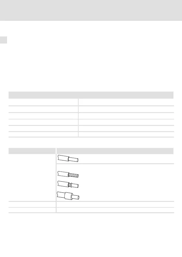
Terminal data
Electrical connection Plug connector with screw connection
Possible connections
rigid: 1.5 mm
2
(AWG 16)
flexible:
without wire end ferrule
1.5 mm
2
(AWG 16)
with wire end ferrule, without plastic sleeve
1.5 mm
2
(AWG 16)
with wire end ferrule, with plastic sleeve
1.5 mm
2
(AWG 16)
Tightening torque 0.5 ... 0.6 Nm (4.4 ... 5.3 lb-in)
Bare end 6mm
 Loading...


