Installation
4-23
BA9300SU EN 2.1
Connection of digital signals
Analog signals are connected via the 2 x 7-pole terminal block X5.
The levels of the digital inputs and outputs are PLC compatible.
Only use relays with low-current contacts for the switching of the signal cables
(recommendation: relays with gold-plated contacts).
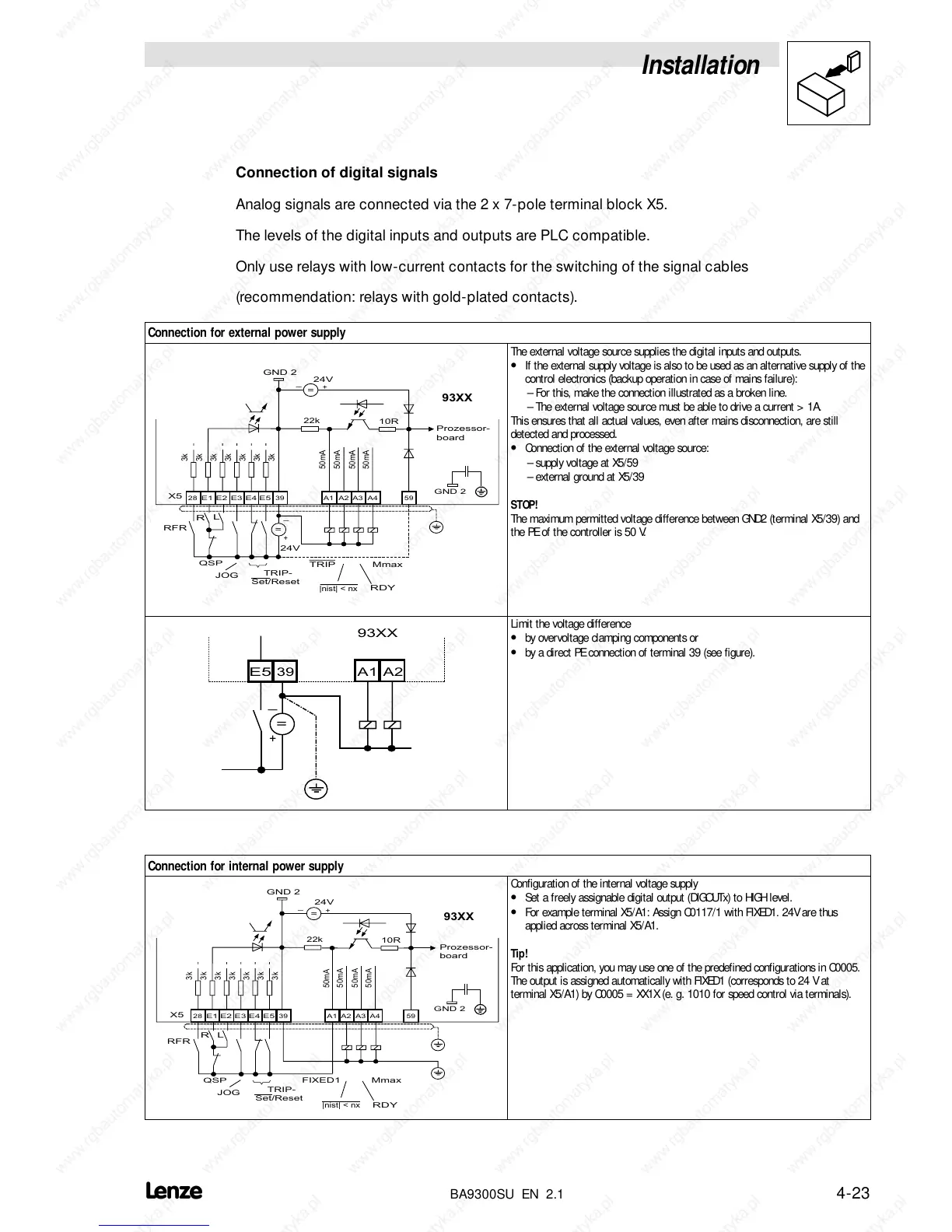
Connection for external power supply
A3
28
E1 E2 E3 E4 E5
A1
A2
59
_
39
22k
10R
R
L
GND 2
+
QSP
JOG
TRIP-
Set/Reset
TRIP
RDY
|nist| < nx
Mmax
3k
3k
3k
3k
3k
3k
3k
50mA
50mA
50mA
50mA
A4
RFR
X5
+
_
=
=
24V
24V
Prozessor-
board
93XX
GND 2
The external voltage source supplies the digital inputs and outputs.
• If the external supply voltage is also to be used as an alternative supply of the
control electronics (backup operation in case of mains failure):
– For this, make the connection illustrated as a broken line.
– The external voltage source must be able to drive a current > 1A.
This ensures that all actual values, even after mains disconnection, are still
detected and processed.
• Connection of the external voltage source:
– supply voltage at X5/59
– external ground at X5/39
STOP!
The maximum permitted voltage difference between GND2 (terminal X5/39) and
the PE of the controller is 50 V.
E5
A1
A2
_
39
+
=
93XX
Limit the voltage difference
• by overvoltage clamping components or
• by a direct PE connection of terminal 39 (see figure).
Connection for internal power supply
A3
28
E1 E2 E3 E4 E5
A1
A2
59
39
22k
10R
R
L
GND 2
QSP
TRIP-
Set/Reset
RDY
|nist| < nx
FIXED1
3k
3k
3k
3k
3k
3k
3k
A4
RFR
X5
50mA
50mA
50mA
50mA
+
_
24V
=
Prozessor-
board
JOG
93XX
Mmax
GND 2
Configuration of the internal voltage supply
• Set a freely assignable digital output (DIGOUTx) to HIGH level.
• For example terminal X5/A1: Assign C0117/1 with FIXED1. 24V are thus
applied across terminal X5/A1.
Tip!
For this application, you may use one of the predefined configurations in C0005.
The output is assigned automatically with FIXED1 (corresponds to 24 V at
terminal X5/A1) by C0005 = XX1X (e. g. 1010 for speed control via terminals).

 Loading...