Installation
4-13
L MA9300PLC EN 1.4
4.2.7 Power connections
Controllers Preparations for power connection
9321 ... 9326 • Remove the covers of the power connections:
– Unlatch to the front by gentle pressure.
– Pull upwards (mains connection) or downwards (motor connection).
9327 ... 9332 • Remove cover:
– Loosen screws (X) (see Fig. 4-1).
– Swing cover to the top and detach.
– Take the accessory kit out of the interior of the controller.
4.2.7.1 Mains connection
Types 9321 to 9326 Types 9327 to 9332
PE
L1 L2 L3
-UG+UG
➀
➁
PE
+UG
-UG
L1
L2
L3
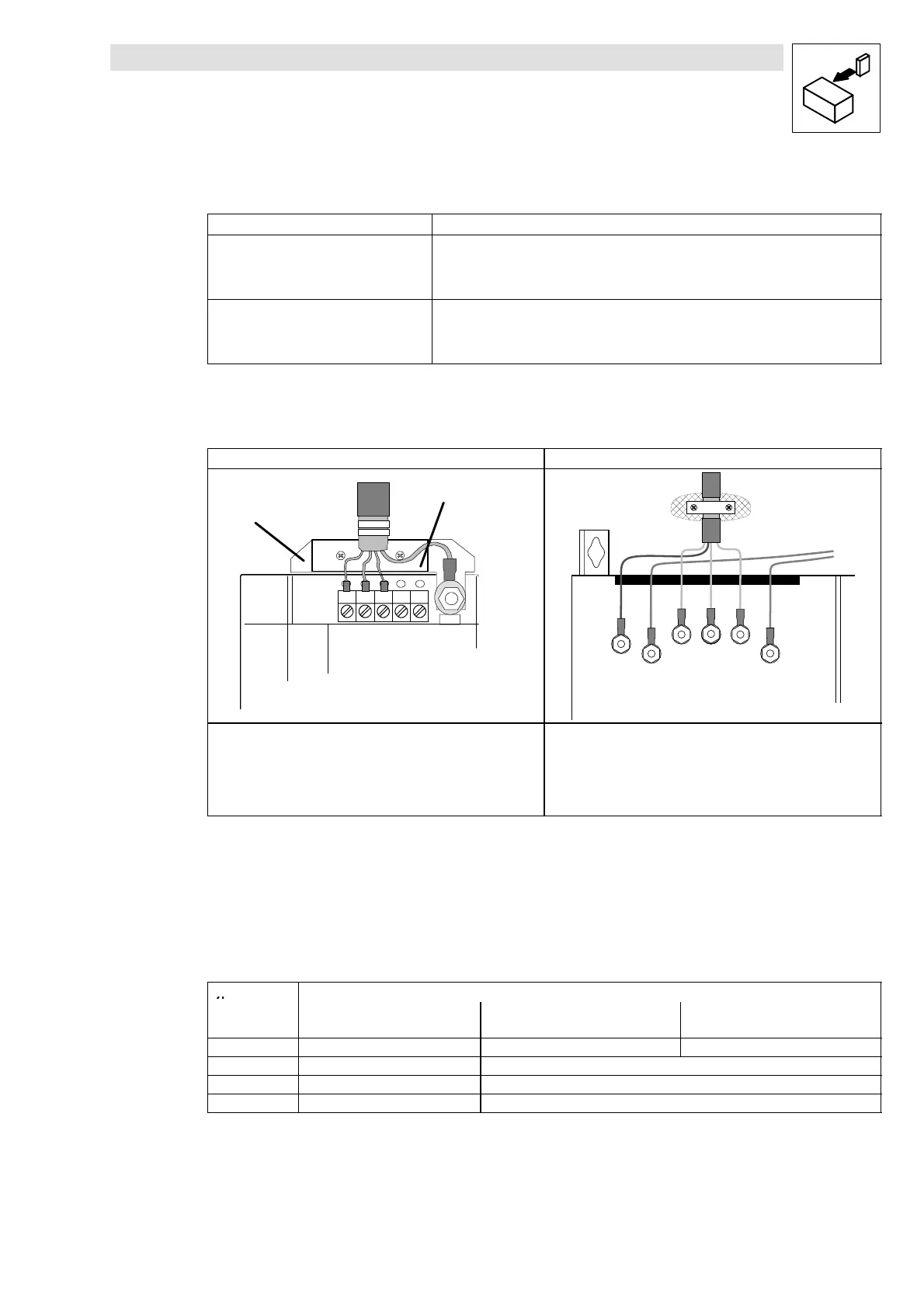
Correct shield connection with shielded cables
(required parts in the accessory kit):
• Screw shield plate Q on fixing bracket. R
• Fix shield using cable lugs. Do not use as a strain relief!
• To improve the shield connection: Connect shield additionally at the
PE stud next to the power connections.
Make a correct shield connection with shielded cables:
• Connect the shield with suitable clamp on the conducting control
cabinet mounting plate.
• To improve the shield connection: Connect shield additionally to the
PE stud next to the power connections.
Fig. 4-7 Proposal for a mains connection
• Connect mains cables to screw terminals L1, L2, L3.
• Connect cables for brake unit (935X), supply module (934X) or further controllers in DC-bus
connection to the screw terminals +UG, -UG at the top of the controller.
• Max. permissible cable cross-sections and screw tightening torques:
Type Terminals
Max. permissible
cable cross-sections
L1, L2, L3, + UG, -UG PE connection
9321 - 9326 4mm
21)
0.5 ... 0.6 Nm (4.4 ... 5.3 lb-in) 3.4 Nm (30 lb-in)
9327 - 9329 25 mm
22)
5Nm(44lb-in)
9330 - 9331 95 mm
22)
15 Nm (132 lb-in)
9332 120 mm
22)
30 Nm (264 lb-in)
1)
with pin cable lug: 6 mm
2
with wire crimp cap 4 mm
2
2)
with ring cable lug Cross-section is only limited by cable entry in the housing
 Loading...


