Installation
4-22
L
MA9300PLC EN 1.4
4.2.8.3 Connection diagrams
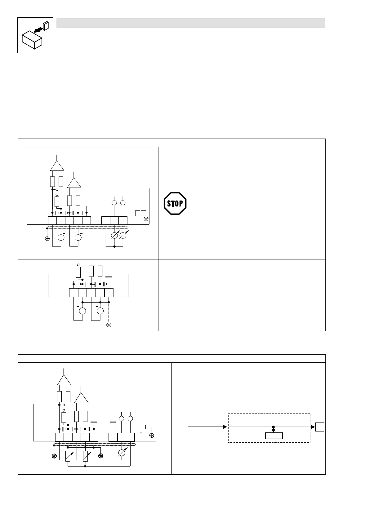
Connection of analog signals
Analog signals are connected via the 2 x 4-pole terminal block X6.
Depending on the use of the analog inputs, the jumper of X3 must be set accordingly.
Connection for external voltage supply
+
1234 7 63
100k
100k
100k
X6
GND1 GND1
+
X6
3,3nF
100k
7
U
62
U
242R
X3
93XX
==
GND1
• The maximum permitted voltage difference between an external
voltage source and the GND1 (terminal X6/7) of the controller is
10V (common mode).
• The maximum permitted voltage difference between GND1
(terminal X6/7) and the PE of the controller is 50 V.
+
1234
100k
GND1
+
X6
3,3nF
100k
7
242R
==
93XX
Limit the voltage difference
• by overvoltage clamping components or
• by direct connection of terminal(s) X6/2, X6/4 and X6/7 to GND1 and PE (see
diagram).
Connection for internal voltage supply
1234 7 63
100k
100k
100k
X6
GND1
GND1
X6
3,3nF
100k
7
U
62
U
242R
X3
10k
10k
93XX
GND1
• Configuration of the internal voltage supply
– A 10 VDC voltage is applied to terminal X6/63 if the analog output is
programmed with DDC as follows:
1234 7 63
100k
100k
100k
X6
GND1
GND1
X6
3,3nF
100k
7
U
62
U
242R
X3
10k
10k
93XX
GND1
K35.118
9300PLC001
C 4 3 9 / 1
6 3
A O U T 2
A O U T 2 _ n O u t _ a
X 6
1 6 3 8 4
 Loading...


