Installation
4-18
L
MA9300PLC EN 1.4
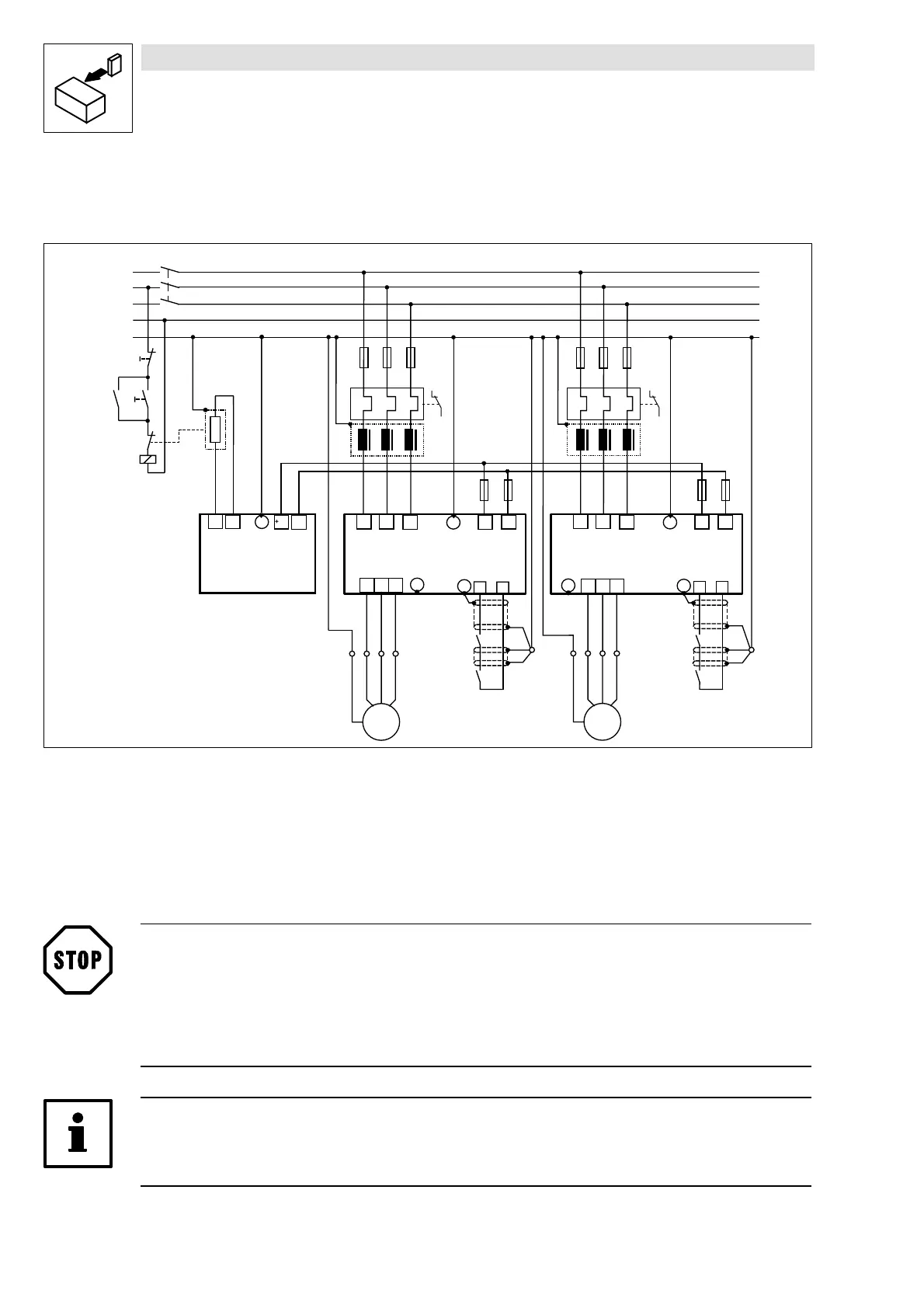
4.2.7.4 DC-bus connection of several drives
Decentralized supply with brake module
K 1
K 1
L 3
N
P E
L 1
L 2
U
V
W
M
3 ~
P E
L 1 L 2 L 3
F 1
9 3 2 X - 9 3 3 X
P E
+ U G - U G
P E
R B
J
+ U G
- U G
9 3 5 2
P E
R B 2
R B 1
Z 1
X 1
Z 3
R B
K 1
U
V
W
M
3 ~
P E
L 1 L 2 L 3
9 3 2 X - 9 3 3 X
P E
+ U G
- U G
P E
Z 2
F 7
F 8
F 9 F 1 0
O N
O F F
2 8
A 4
P E
2 8
A 4
K 1
R F R
P E
X 2
K 1
R F R
F 2 F 3
F 4
F 5 F 6
Z 4
K35.0113
Fig. 4-9 Decentralized supply for DC-bus connection of several drives
Z1, Z2 Mains filter (for dimensioning see systems manual, part F)
Z3 Brake chopper
Z4 Brake resistor (for r.m.s. current monitoring see systems manual, part F)
F1...F6 Fuses (see chapter 3.4.4 and chapter 4.2.7.1)
F7...F10 DC-bus fuses (see chapter 3.4.4 / 4.2.7.1); fuse holder with / without alarm contact
K1 Main contactor
Stop!
• Set the DC-bus voltage thresholds of controller and brake unit to the same values.
– Controller using C0173
– Brake unit using switches S1 and S2
• A bimetal relais is required for monitoring the mains supply.
Tip!
Please observe the specifications in part F of the Manual and the application report “DC-bus
connection” for the dimensioning and rating of the components.
 Loading...


