Electrical installation
Plug connectors
Motor plug connection assignment
6
32
Lenze ¯ BA 33.0005 ¯ 5.0
6.5 Plug connectors
Stop!
¯ Tighten the coupling ring of the connector.
¯ If plugs without SpeedTec bayonet nut connectors are used, the
connector boxes for the power / encoder / fan connections must be
secured by O−rings if loadings by vibration occur:
– M17 connector box with O−ring 15 x 1.3 mm
– M23 connector box with O−ring 18 x 1.5 mm
Plug−in connectors (plug/connector box) with SpeedTec bayonet nut
connectors are vibration−proof.
¯ If SpeedTec bayonet nut connectors are used, O−rings must be
removed (if any)!
¯ Never disconnect plugs when voltage is being applied! Otherwise, the
plugs could be destroyed! Inhibit the controller before disconnecting
the plugs!
6.5.1 Motor plug connection assignment
Note!
When making your selection, the motor data and permissible currents of
the cables according to the system cable system manual must be
observed.
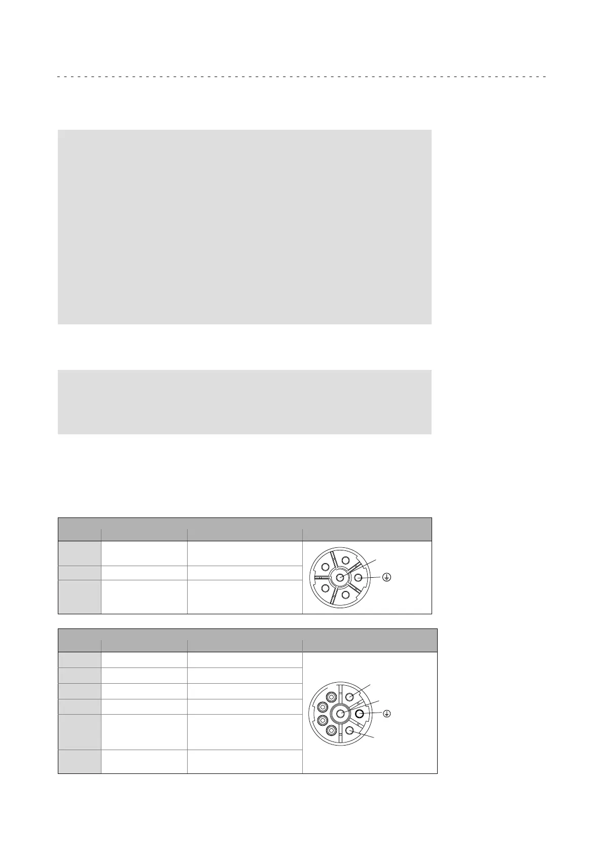
6.5.2 Power connections
Power / brake / thermal sensor
ICN, 6−pole and 8−pole
6−pole (external view of poles)
Contact Name Meaning M23
1
2
BD1 / BA1
BD2 / BA2
Brake + / ~
Brake − / ~
MT−Steckverbinder−001.iso/dms
1
2
4
5
6
PE PE conductor
4
5
6
V
V
W
Power phase U
Power phase V
Power phase W
8−pole (external view of poles)
Contact Name Name M23
1 V Power phase U
MT−Steckverbinder−001.iso/dms
4
1
A
B
C
D
PE PE conductor
3 W Power phase W
4 V Power phase V
A
B
TB1 / TP1 / R1
TB2 / TP2 / R2
Thermal sensor:
TCO / PTC / + KTY
TCO / PTC / − KTY
C
D
BD1 / BA1
BD2 / BA2
Brake + / AC <250 V
Brake − / AC <250 V
 Loading...