3. TECHNICAL BRIEF
3.3.2 UMTS TRANSMITTER
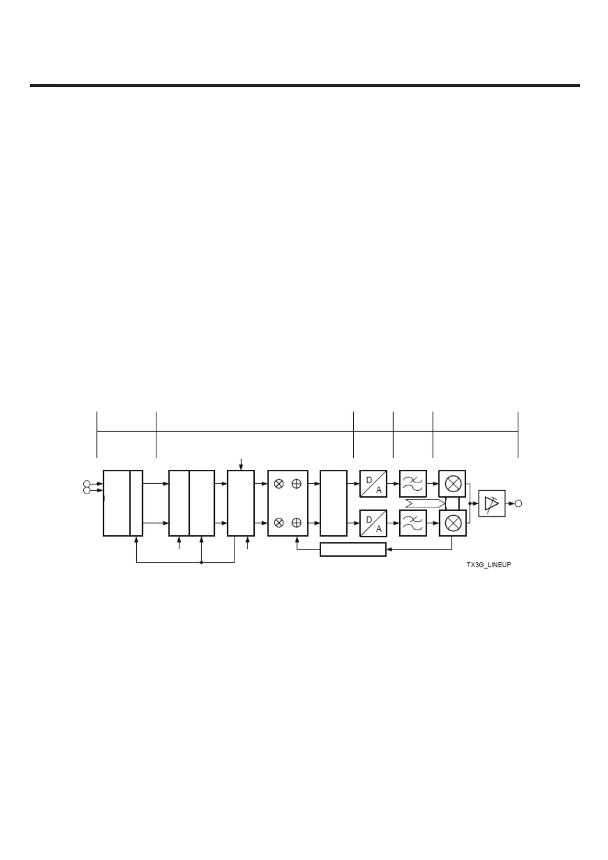
Figure 3-6 shows a functional overview of the 3G transmitter chain implemented for RF signal processing. The
IQ-chips, which are transferred via the digital interface, are stored in a FIFO. Then it depends on the setting of
three signals how samples are consumed from the FIFO Buffer.
Then the samples are fed into a CORDIC, which is used to shift the phase of the complex signal. The root-
raisedcosine (RRC) filter performs the pulse shaping according to 3GPP. As the system clock is no integer
multiple of the UMTS chip rate a fractional sample rate conversion (FSRC) is necessary. In the amplitude
correction / offset correction (AC/OC) block the amplitude and the offset of the IQ-signal are modified.
The final sample rate at the output of the digital front end is achieved in the interpolation / noise shaping block,
where also the word length is reduced in order to fit to the D/A-converter resolution. After the DAC a post-filter
reduces the level of the repetition spectrum and the analog noise in order to supply a clean signal to the IQ-
modulator. The frequency conversion to the wanted TX-channel is done in a direct-up conversion IQ-modulator
which is followed by a gain stage with a single ended high power output.
[Figure 3-6] 3G Transmitter Line Up

 Loading...