11
General Installation Guidelines
Due to our policy of continuous product innovation, some specifications may change without notification.
©LG Electronics U.S.A., Inc., Englewood Cliffs, NJ. All rights reserved. “LG” is a registered trademark of LG Corp.
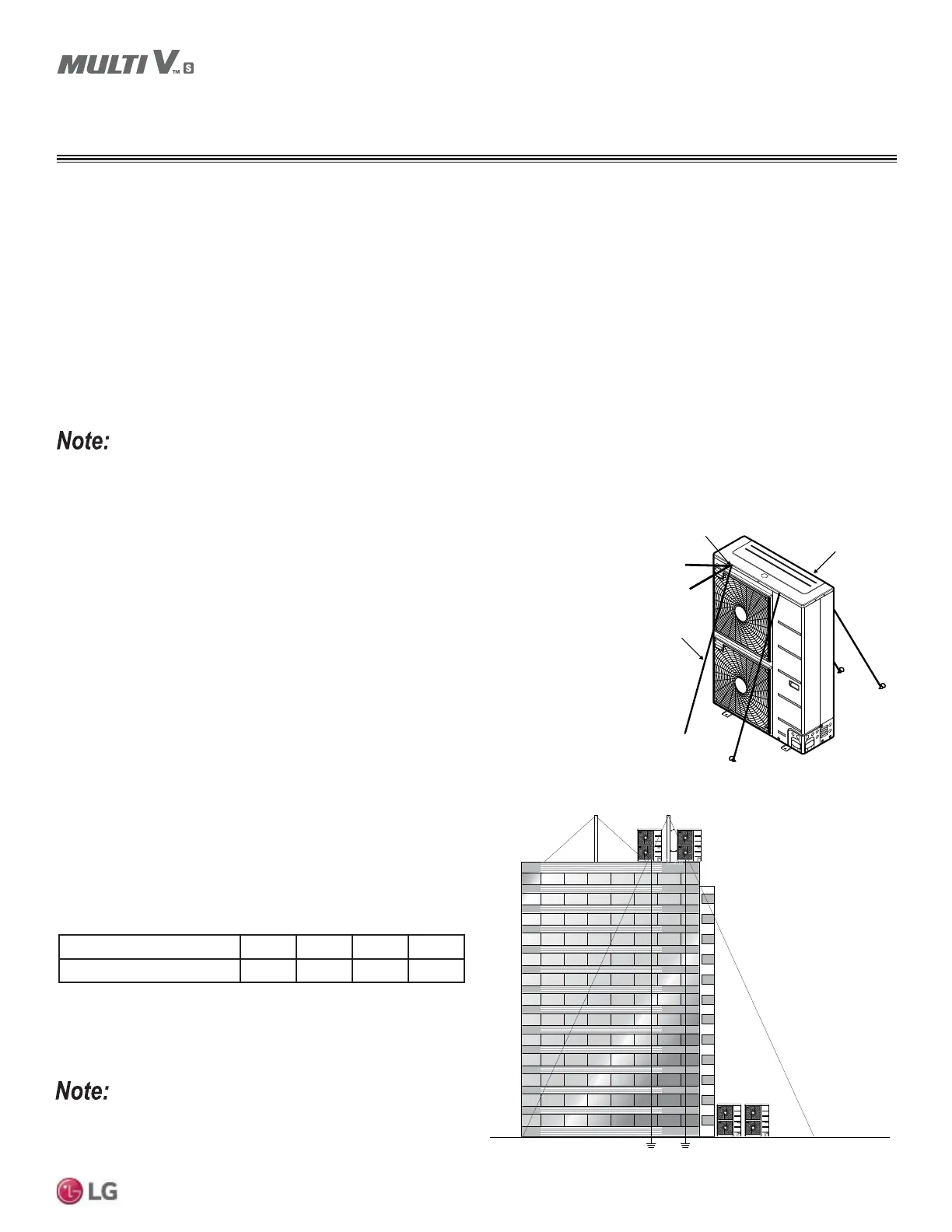
Tie-Downs and Lightning Protection
7LH'RZQV
• The strength of the roof must be checked before installing the
outdoor units.
• If the installation site is prone to high winds or earthquakes, when
installing on the wall or roof, securely anchor the mounting base
using a field-provided tie-down configuration approved by a local
professional engineer (see diagram at right for example).
• Use four wires, deattach the top of the frame at the locations
indicated, thread the screws through the wires, then reattach the
screws to the outdoor unit frame.
• The overall tie-down configuration must be approved by a local
professional engineer. Always refer to local code when using a
wind restraint system.
Lightening Protection
• To protect the outdoor unit from lightning, it should be placed within
the specified lightning safety zone.
• Power cable and communication cable should be installed five (5)
feet away from lightning rod.
• A high-resistance ground system should be included to protect
against induced lightning or indirect strike.
Ground
Safe zone
Lightning rod
Protection Angle (25˚~55˚)
1.5m
5 feet
Lightning rod
Figure 1: Lightning Protection Diagram.
Table 3: 6DIHW\=RQH6SHFL¿FDWLRQV
%XLOGLQJ+HLJKWIHHW 66 98 148 197
3URWHFWLRQ$QJOHÜ 55 45 35 25
If the building does not include lightning protection, the outdoor unit
may be damaged from a lightening strike. Inform the customer of this
possibility in advance.
Rooftop Installations
If the outdoor unit is installed on a roof structure, be sure to level the unit. Ensure the roof structure and anchoring method are adequate for
the unit location. Consult local codes regarding rooftop mounting.
Dealing with Snow and Ice
In climates that experience snow buildup, place the unit on a raised platform to ensure proper condenser airflow. The raised support platform
PXVWEHKLJKHQRXJKWRDOORZWKHXQLWWRUHPDLQDERYHSRVVLEOHVQRZGULIWV0RXQWWKHXQLWRQDILHOGSURYLGHGVWDQGWKDWLVKLJKHUWKDQWKH
maximum anticipated snowfall for the location. Design the mounting base to prevent snow accumulation on the platform in front or back of the
unit case. If necessary, provide a field fabricated hood to keep snow and ice and/or drifting snow from accumulating on the coil surfaces. Use
inlet and discharge duct or hoods to prevent snow or rain from accumulating on the fan inlet and outlet guards. Best practice prevents snow
from accumulating on top of the unit. Consider tie-down requirements in case of high winds or where required by local codes. In all cases,
connected duct work and accessories must provide a combined air pressure drop rating that does not exceed 0.16” WG.
• When deciding on a location to place the outdoor unit, be sure to choose an area where run-off from defrost mode will not
accumulate and freeze on sidewalks or driveways.
• Snow throw mode does not prevent ice from forming on the fan blade or discharge grille.
GENERAL INSTALLATION GUIDELINES
Location for Outdoor Unit
Location of the Front
Attachment Holes
Wires
Location of the Rear
Attachment Holes
Figure 2: Lightening Protection Diagram.
 Loading...