52
MULTI V S System Installation Manual
Due to our policy of continuous product innovation, some specifications may change without notification.
©LG Electronics U.S.A., Inc., Englewood Cliffs, NJ. All rights reserved. “LG” is a registered trademark of LG Corp.
WIRING
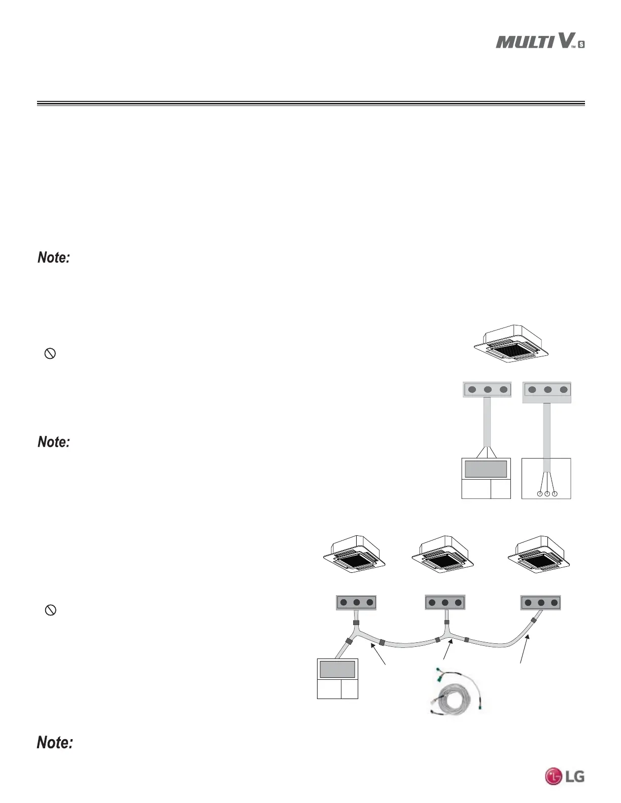
Cable connected to Zone Controller is the factory default connection.
Communication Cables Between the Outdoor Unit(s) and the Central
Controllers
Communication Cables Between the Indoor Units and the Wall-Mounted Zone
Controller
&RQQHFWWKHVKLHOGWRJURXQG21/<DWWKHRXWGRRUXQLW7LHVKLHOGVWRJHWKHUDWHDFKWHUPLQDWLRQSRLQW
• Only use LG provided three-core communications cable between the indoor unit and the wall-mounted
zone controller.
•
NEVER splice, cut, or extend cable length with field provided cable. If the length needs to be
extended, the LG Extension Kit (sold separately) must be used. A maximum of four (4) kits (up to 165
feet) can be used.
• Set the indoor unit operating parameters using DIP switches or by setting up the zone controller. Refer
to the indoor unit installation manuals for more details.
Cable connected to Zone Controller is the factory default connection.
• AC EZ Simple Central Controllers: Field-Provided, 18 Gauge, Stranded Four-Core Communication Cable (shielded).
• All Other Central Controllers: Field-Provided 18 Gauge, Stranded Two-Core Communications Cable (Shielded).
• Insulation material as recommended by local code.
• Separate communications cables and power wiring. See Table 30 for appropriate distances.
Connect all central control devices such as AC products, ACPs, BACnet and LonWorks gateways, and energy recovery ventilators all on the
same cable. Order does not matter. Polarity does. Keep “A” terminals with “A” terminals, and “B” terminals with “B” terminals. Starting at the
outdoor unit, terminate the cable on terminals Internet A and Internet B. Route the cable as needed between each device.
CN-REMO
On All Indoor Unit Styles
RD
BK
YL
LG Supplied
Front
CN-REMO
RDBKYL
Back
Figure 62: Indoor Unit to Zone
Controller Connection.
Communication Cables Between Multiple Indoor Units
Operating as a Group (Group Control)
• If any indoor units were specified to operate in unison, use one (or
multiple) three-core Group Control Kit (sold separately) containing
extension and Y-splitter cables. One (1) group control cable kit for
each indoor unit in the group except for the last indoor unit.
• Always use an LG provided group control communications cable
(Group Control Kit; sold separately) between the indoor unit and
the wall-mounted zone controller.
•
NEVER splice, cut, or extend cable length with field provided
cable.
• %HIRUHUXQQLQJFDEOHGHFLGHZKLFKLQGRRUXQLWZLOOEHWKH³0DVWHU´
7KH]RQHFRQWUROOHUZLOOEHFRQQHFWHGWRWKH³0DVWHU´
• ,GHQWLI\HDFKLQGRRUXQLWRSHUDWLQJDVDJURXSDV³0DVWHU´RU
“Slave”. Adjust the pertinent DIP switch at each indoor unit. On
wall mounted indoor unit models, set the assignment using the
handheld remote controller.
• 8VHDGDLV\FKDLQFRQILJXUDWLRQDQGFRQQHFWDOORIWKHJURXS¶V
LQGRRUXQLWVWRJHWKHUVWDUWLQJDWWKH³0DVWHU´XQLW
CN-REMO
On All Indoor Unit Styles
CN-REMO
On All Indoor Unit Styles
CN-REMO
On All Indoor Unit Styles
LG
Supplied
LG Supplied Group Control Kit (PZCWRCG3)
Figure 63: Indoor Unit Group to Zone Controller Connections.
&RPPXQLFDWLRQV&DEOH6SHFL¿FDWLRQV
 Loading...