148
MULTI V 5 Outdoor Unit Service Manual
Due to our policy of continuous product innovation, some specifications may change without notification.
©LG Electronics U.S.A., Inc., Englewood Cliffs, NJ. All rights reserved. “LG” is a registered trademark of LG Corp.
ERROR CODES
Please refer to the Safety Precautions on pages 4-7 for more detail to prevent injury or death regarding the operation and service
troubleshooting of the Multi V product.
WARNING
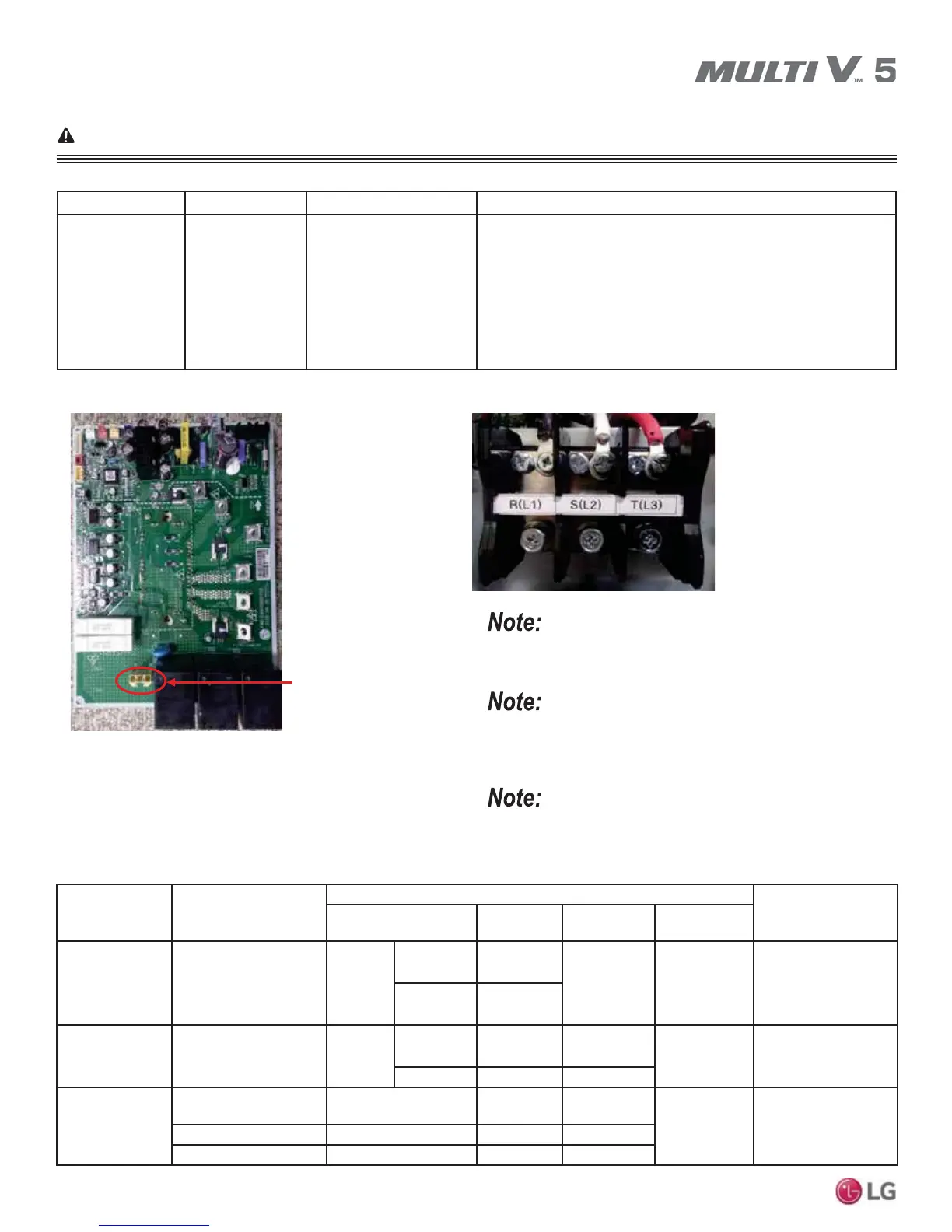
Error No. 23
Error No. Description Details Causes
23
Master: 231
Slave 1: 232
Slave 2: 233
Low DC voltage
sensed at the out-
door unit inverter
compressor DC
link.
System shut off because
the DC link voltage fell
below 50V (for both 208-
230V and 460V units), or
exceeded 550V (for 208-
230V units) or 1,000V (for
460V units) for a minimum
of 250μs.
1. Start diagnosis at the inverter socket on the outdoor unit noise
filter PCB.
2. There is a capacitor that is not working properly, or the voltage at
the capacitor is out of range (either high or low).
3. Disconnected DC link.
4. Damaged electrical condenser component (serving capacitor) on
inverter driver board.
Check DC link connections.
DC Link Connector
Measure input voltage.
Images here are representative of system components. Actual compo-
nent appearance depends on model and system type.
Cause Check
Checklist
App.
Check Point Normal Abnormal
Defective
Parts
Input
Voltage Abnormal
Check Input Voltage
Voltage
3P3W, 220V 220V ± 15%
Non-normal Input Voltage
A1
(Power ON)
3P3W, 460V 460V ± 15%
DC Link
Power Abnormal
Check DC Link Voltage Voltage
3P3W, 220V 310V±20% 9Ļ9Ĺ
Converter
PCB
A3
(Power ON and
Compressor operating)
3P3W, 460V 650V±20% 9Ļ9Ĺ
Converter
PCB damaged
Check Converter PCB
Appearance
Appearance Good Damage
Converter
PCB
B2
(Power Off)Measure 5V,15V line 5V, 15V Resistance NĹ NĻa
Check Bridge Diode P-R,S,T / N-R,S,T 0.38V ~ 0.7V Non-normal
Table 79: Error No. 23 Checkpoint Details.
Always apply heat transfer paste to the new inverter PCB heat sink
before installing. For instructions, see “Replacing the Inverter PCB Heat
Sink” page later in this section.
See the “Checking the Inverter Insulated-Gate Bipolar Transistor Mod-
ule” and the “Checking the Phase Diode Bridge” pages in the “Trouble-
shooting Main Components” section.

 Loading...