97
PCB Settings
Due to our policy of continuous product innovation, some specifications may change without notification.
©LG Electronics U.S.A., Inc., Englewood Cliffs, NJ. All rights reserved. “LG” is a registered trademark of LG Corp.
Addressing with Heat Recovery Units
(For Heat Recovery Systems Only)
General
Each heat recovery unit will have a unique address assign so the
outdoor unit will be able distinguish it from other heat recovery units.
Upon completion of the heat recovery unit address, the heat recov-
ery unit operating parameters will be set by adjusting the positions
DIP switches on SW02M and SW01M.
Procedure
Before beginning the physical process of assigning heat recovery
addresses, map out the address assignments using a copy of the
LATS tree mode diagram.
Guidelines
1. Addresses must be sequential and cannot be skipped.
2. Assign the lowest address to the heat recovery unit that has the
largest capacity indoor unit connected to port number 1. If the
capacity of all indoor units connected to port number 1 of each heat recovery unit is the same, assign address “0” to the heat recovery
unit farthest away from the outdoor unit. Assign the next address to the next farthest away and so on until all heat recovery units have an
address. The heat recovery unit with the highest address must be the one closest to the outdoor unit. Up to 16 heat recovery units can be
on a single system.
Possible settings in order of lowest to highest are: 0,1,2,3,4,5,6,7,8,9,A,B,C,D,E,F.
Addressing must be performed following the detailed steps above because port number 1 on the heat recovery unit addressed “0” will remain open
during the auto pipe detect procedure. If the indoor unit capacity connected to the port is relatively small compared with other units on the system,
the outdoor unit high head pressure safety will trip and shut down the unit during the procedure. On LGMV, all addresses do not match because
LGMV does not see address “0”.
3. Record the address assigned to each heat recovery unit.
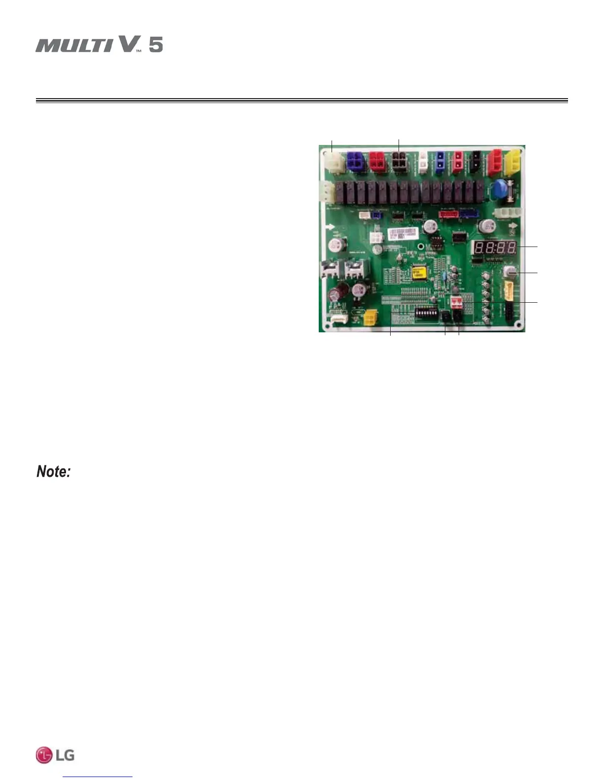
Figure 43: Heat Recovery Unit Main PCB.
Air Valve Housing
SSD
SW05M
SW01M
SW04MSW03M
(SW01M / SW03M / SW04M
Switches for Manual Valve Addressing)
SW02M
(DIP Switch for Set Up of Heat
Recovery Unit Functions)
No. 1 Valve Housing
HEAT RECOVERY UNIT SETTINGS