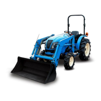
(2) Upper link installation and
adjustment
Select the attaching hole depending on the draft
load of the implement.
The upper hole is more sensible than lower one.
Adjust the length of the upper link(3) using the
knob(4) after releasing the locking nut (7).
After the adjustment, fasten it with the locking nut
(7).
Adjustment range : 480 ~ 700 mm (18.9 ~ 27.6 in)
①⑥
①⑥①⑥
①⑥
④
④④
④
③
③③
③
②
②②
②
⑤
⑤⑤
⑤
⑦
⑦⑦
⑦
▶
To keep the upper link pin(5) from being escaped, be sure to fix the snap pin(6).
Notice
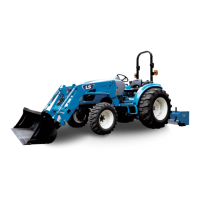
(3) Adjustment of the lift rod’s
length (Left/ Right)
For lift rod (LH), detach the upper side from the lift
arm and adjust the length by turning the upper
side (1).
For lift rod (RH), lift up the handle(4) and turn it to
the right to shorten the rod. In case of turning to
the left, the rod is elongated.
After the adjustment, pull down the handle(4) and
fix it firmly.
Adjustment range : 430 ~ 540 mm (16.9 ~ 21.3 in)
④
④④
④
③
③③
③
①
①①
①
②
②②
②
①
①①
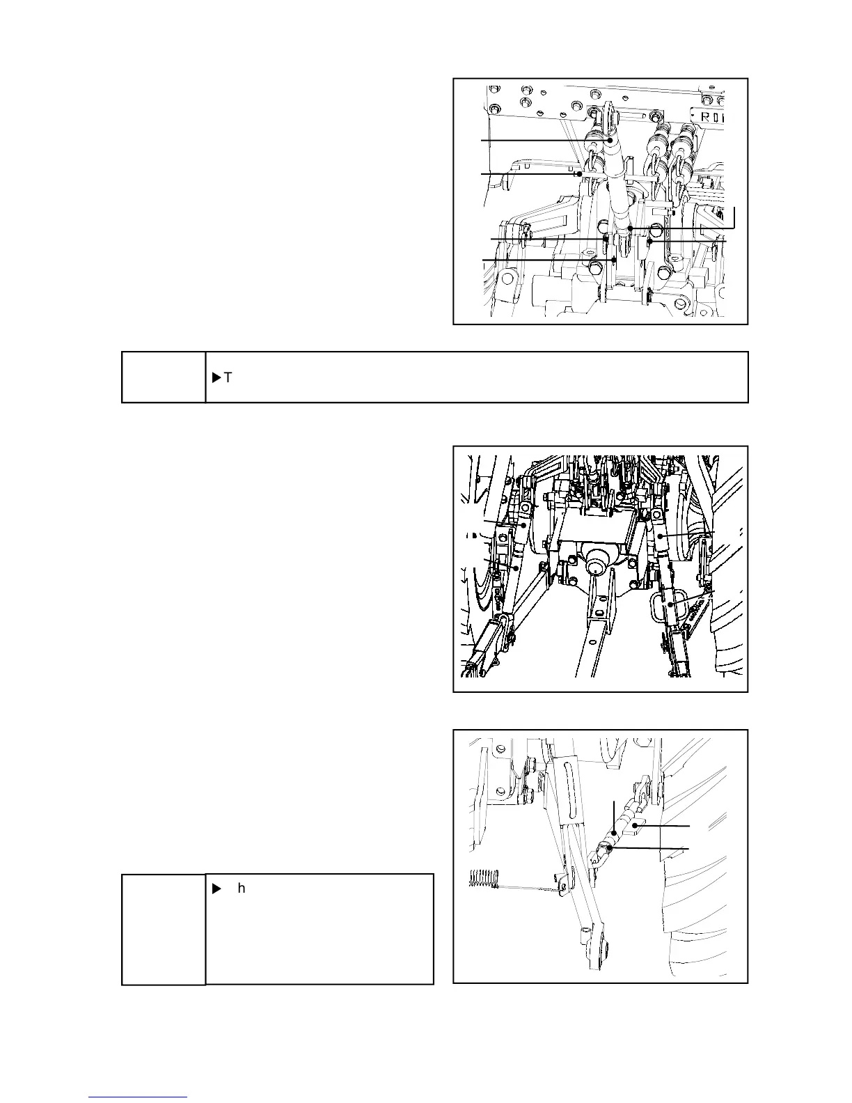
① Check chain type
Turn the knob(2) to adjust the length of the
stabilizer(1). After the adjustment , let it tightened
firmly by fixing nut(1).
▶
When adjusting the stabilizer’s
length, adjust the implement’s
swinging clearance to be
20~40mm (0.79~1.57 in.) left
and right.
Notice
①
①①
①
③
③③
③
②
②②
②

 Loading...