Connections
Snow depth sensor SHM 31, V2.1 17
6. Connections
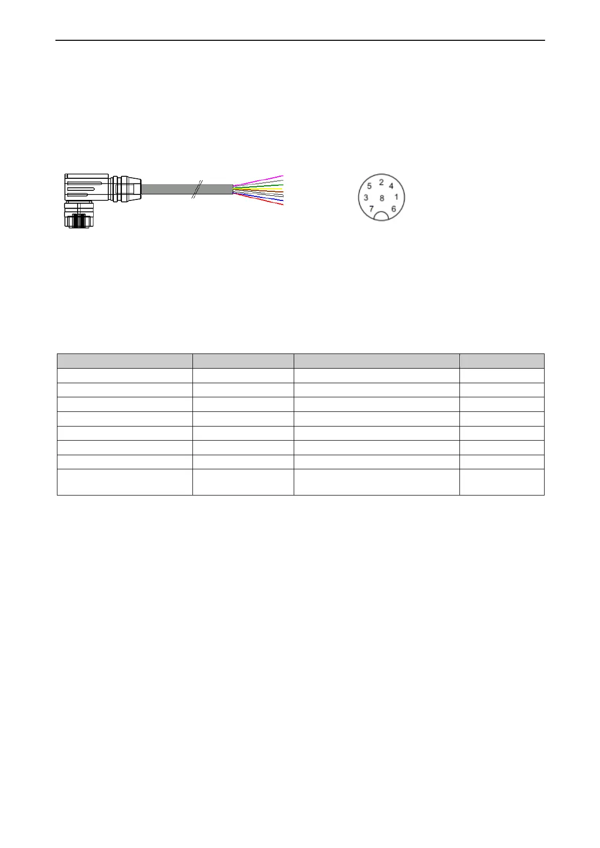
There is an 8-pin plug-in screw connector on the device’s housing. It is used to connect the supply voltage
and the data interface.
A connection cable measuring 15 m long is offered separately.
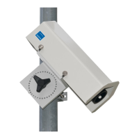
6.1. Connecting the device
T
he Amphenol C091D series connector has a locking ring (white). Loosening the ring enables variation of the
direction of the cable outlet to the notch in increments of 45°.
6.2. Connector pin assignment
RS485 B / SDI-12 Data Line
Supply voltage –
SDI-12 ground
Table 1: SHM 31 connector pin assignment
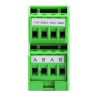
6.3. Recommended cable shield connection
The shielding of the SHM 31’s connection cable must be connected to earth in the switch box, as there is
usually no secure, electrically conductive connection to an earthed mast via the screw joints and mast clamp.
6.4. Supply voltage
The snow depth sensor is supplied with a DC voltage of
12 V DC ±15% or 24 V DC ±15%.
6.5. Data interfaces
The device has a half-duplex, two-wire RS485 interface for measured value queries and firmware updates,
an SDI-12 interface, and an RS232 interface.
6.6. Heating release
The sensor can be configured such that the heating is only switched on after a positive voltage signal
(typically 5 – 12 V DC with 12 V DC operating voltage or 24 V DC with 24 V DC operating voltage) has been
applied. This allows the user to operate the heating in battery mode, for example, regardless of the internal
heating configuration.
16: Connection cable (schematic), designation of the
Figure 17: View of soldered connection of
the cable box with notch.
 Loading...