Grove Published 11-10-2014, Control # 524-00 6-17
RT880E SERVICE MANUAL SWING SYSTEM
2. Disconnect the batteries. (Refer to Batteries, page 3-3.)
3. Locate the connectors which join the collector ring har-
ness to the receptacles for the carrier.
4. Tag the connectors and their receptacles with numbers.
Disconnect the connectors from the chassis wiring
receptacles.
5. Remove the clamp securing the wiring harness to the
retainer plate on the bottom of the hydraulic swivel
assembly.
6. Secure the connectors and wires from each of the num-
bered connectors so the harness can be withdrawn
through the center of the hydraulic swivel.
7. Tag and disconnect the connectors from the receptacles
on the cab bulkhead mounting plate.
8. Remove the capscrews and washers, and remove the
cover from the electrical swivel.
9. Loosen the setscrews securing the electrical swivel
mounting tube to the center post on the water swivel.
10. Remove the capscrew and jam nut securing the electri-
cal swivel case to the plate on the case of the water
swivel.
11. Remove the swivel and wiring harness from the crane. If
necessary, remove the spacer bushing from the center
post.
Installation
1. If removed, install the spacer bushing on the center post.
Route the collector core wiring harness through the cen-
ter of the hydraulic and water swivels.
NOTE: The boom should be centered directly over the
front of the crane before adjustment is made to the
slew potentiometer.
2. Slide the electrical swivel mounting shaft onto the center
post.
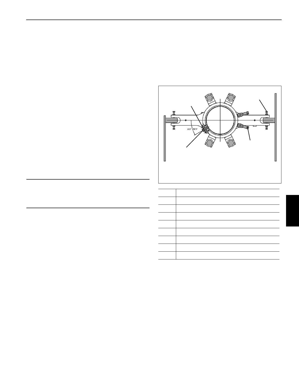
3. Ensure the threaded hole on the bottom of the electrical
swivel base is aligned with the mounting hole in the plate
on the water swivel case. Install the capscrew through
the hole in the plate and install the jam nut. Screw the
capscrew into the hole in the electrical swivel base until
the capscrew head is approximately 0.23 in (6.0 mm)
from the bracket. Tighten the nut against the electrical
swivel (Figure 6-8).
4. Apply medium strength Loctite® to the setscrews secur-
ing the electrical swivel to the center post and tighten
them 44 to 53 lb-in (5 to 6 Nm).
5. Install the swivel cover and secure with capscrews and
washers.
6. Connect the wiring harness connectors to the recepta-
cles on the cab bulkhead mounting plate as tagged dur-
ing removal.
7. Plug the connector into the carrier wiring receptacle,
connect the wires as tagged during removal. Install the
yellow ground wire to the connector mounting bracket on
the carrier frame using the bolt and star washers taken
off at removal. Make sure the ground connection is clean
and has good metal to metal contact. Spray the connec-
tion with a battery terminal protectant such as Deka Bat-
tery Terminal Protection spray, Grove P/N 9999102423.
8. Install the clamp securing the harness to the retainer
plate on the bottom of the hydraulic swivel assembly.
9. Connect the batteries.
CAUTION
When withdrawing the wiring harness through the center
of the hydraulic and water swivels, ensure the wires do
not get caught and damaged.
Item Description
1Hex Nut
2 Capscrew
3 Capscrew
4 Flatwasher
5 Capscrew
6Jam Nut
7 Nipple
8 Adapter
TOP OF SWIVEL
FIGURE 6-8
5, 6
3, 4
7, 8
1, 2
6490-4

 Loading...


