SETUP AND INSTALLATION MLC165-1 OPERATOR MANUAL
4-112
Published 08-06-19, Control # 237-09_v2
Install the Jib Stop
1. Using the fasteners provided, fasten the control cable
guide (Figure 4-85
) to the plate located on the end of the
boom top.
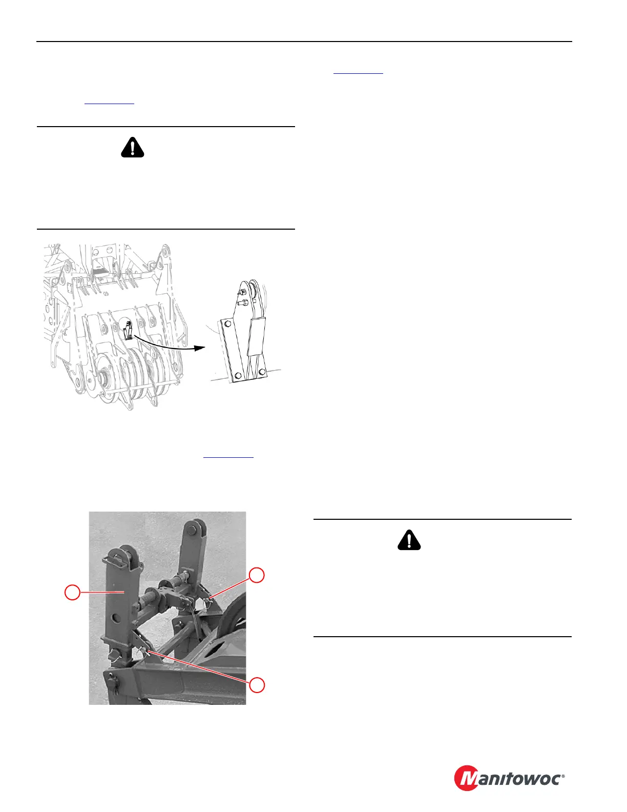
2. Support the jib stop assembly (1, Figure 4-86
), remove
shipping the pins (13) and pivot the assembly down. It
weighs 176 lb (80 kg).
Reinstall the pins (13) onto the jib frame lugs.
See Figure 4-87
for the remaining steps.
3. Attach the jib stop assembly (1) to the lugs on the boom
top using pins (2, View A).
4. Set the jib stop length (View A):
a. Remove the offset pins (3).
b. Adjust the position of the inner tubes (5) so the
holes in the tubes are aligned with the proper offset
holes in the links (4).
c. Reinstall the offset pins (3).
5. Connect the jib stop control cable:
a. Route the control cable extension (8, View E, stored
in the jib butt) through the sheave (9, View A)
located on the boom top.
b. Using the shackle (7, View A), connect the end of
the control cable extension (8) to the control cable
(15, View C) from the jib stop.
c. Using the other shackle (10, View E), connect the
other end of the control cable extension to the
control cable (11) from the winch on the jib top.
6. Use the winch to take the load off the two safety pins (14,
View B) and remove the safety pins.
7. Pay out the control cable to engage the jib stop pins (6,
View C). Then pay out an additional 2 ft (0,6 m) of the
wire rope.
The pins will not engage the holes in the jib stop frame
until the jib point is lifted clear of the ground.
8. Place the safety pins (14, View C) in their storage
location.
9. Install the jib wiring, load lines, and the block-up limit,
wind speed, and position light components.
10. Boom up until the jib point just clears the ground.
Make sure the jib stop pins fully engage the holes in the
jib stop frame as the boom and jib are raised from the
ground.
WARNING
Crushing Injury Hazard!
The jib stop pins are spring-engaged. Do not remove the
safety pins until the jib stop assembly is connected to the
boom top and the control cables are attached and
tensioned.
WARNING
Falling Jib Hazard!
As the boom and jib are raised from the ground, observe
the jib stop pins to make sure they fully engage the holes
in the jib stop frame.
The jib can be pulled over backward if the jib stop pins do
not engage the holes.

 Loading...


