SETUP AND INSTALLATION MLC165-1 OPERATOR MANUAL
4-126
Published 08-06-19, Control # 237-09_v2
LOAD LINE REEVING
Guide Sheaves and Drums
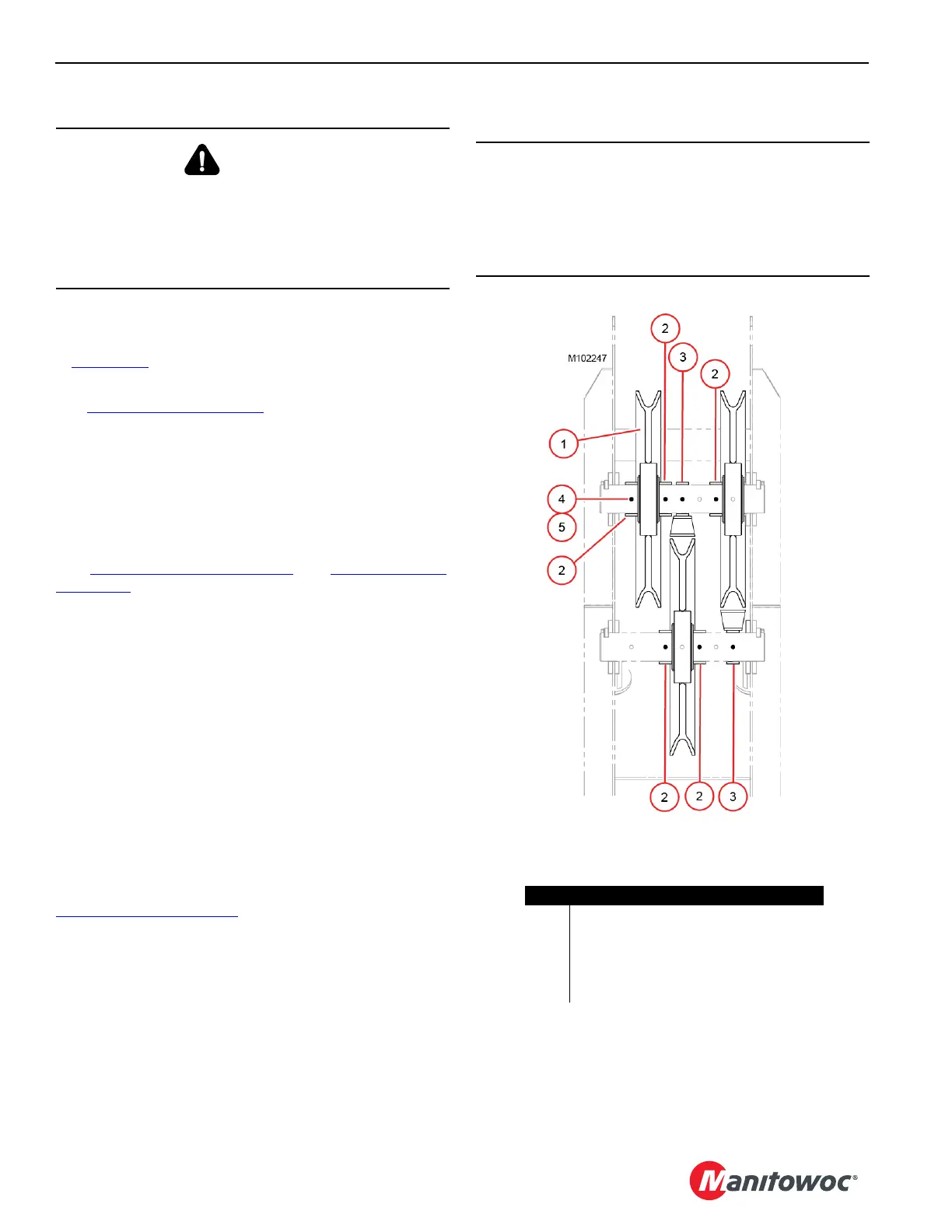
The boom top guide sheaves must be positioned as shown
in Figure 4-98
. The bolts and lock nuts (5) must be inserted
in the black shaded holes.
See Figure 4-99 on page 4-127
for identification of the load
drums and the guide sheaves.
Once the wire rope is routed through the guide sheaves,
install all the rope guard pins, bars, and rollers to retain the
wire rope on the sheaves. Wire rope and sheaves can be
damaged if the rope is not properly retained on sheaves.
Dead End Locations
See Figure 4-100 on page 4-128 and Figure 4-101 on
page 4-129 for the dead end locations.
Load Block Identification
See the Boom Assembly Drawing at the end of this section
for a complete list of load blocks and hook and weight balls
available for use with this crane.
• Parts of the line required to handle desired load
• Wire rope length required for various boom lengths and
parts of line
• Maximum spooling capacity of load hoists
Load Block Reeving
For reeving of the lower boom point, see the Reeving
Diagrams at the end of this section.
For reeving of the fixed jib or upper boom point, see
Figure 4-100 on page 4-128
.
Reeving in any manner other than shown can result in
excessive block twist.
WARNING
Falling Load Hazard!
Use only a load block or hook and weight ball with a
capacity equal to or greater than load to be handled.
The load block can fail if overloaded, allowing the load to
fall.
CAUTION
Wire Rope Damage!
Do not hoist the load block closer to the boom point than
shown on the Range Diagram in the Capacity Chart
Manual. Improper fleet angle or contact with other parts
can damage the wire rope.
Figure 4-98
Item Description
1 Sheave (3)
2 Collar (5)
3 Collar with Guard (2)
4 Alignment Hole (7 each shaft)
5 Bolt with Locknut (7) in Black Holes Only
Viewed from Butt End of Boom

 Loading...


