National Crane Published 4-23-2018 Control # 239-11 3-7
NBT40 SERIES OPERATOR MANUAL OPERATING CONTROLS & PROCEDURES
RCL and Minimum Wrap Bypass Switch
The RCL Bypass Switch (6, Figure 3-3) is a momentary on-
off switch, turn the key to the On position (right) to
disengaged the RCL controls and minimum wrap lockout
controls. Releasing the key allows the RCL and minimum
wrap controls to re-engage.
The RCL and 3 wrap system will be bypassed only as long
as the switch (6, Figure 3-3) is in the On position.
Turning the key switch (6, Figure 3-3) to the On position re-
engages the boom down, telescope out and hoist controls.
These functions were disabled when an overload condition
was sensed by the Rated Capacity Limiter (RCL). It is
important to read and understand the RCL Override Warning
information in the RCL Operator’s Manual before using the
RCL Bypass switch (6) or the RCL on/off switch.
The bypass switch (6, Figure 3-3) will also re-engage the
main and auxiliary hoist controls disabled by the minimum
wrap indicator sensor system.
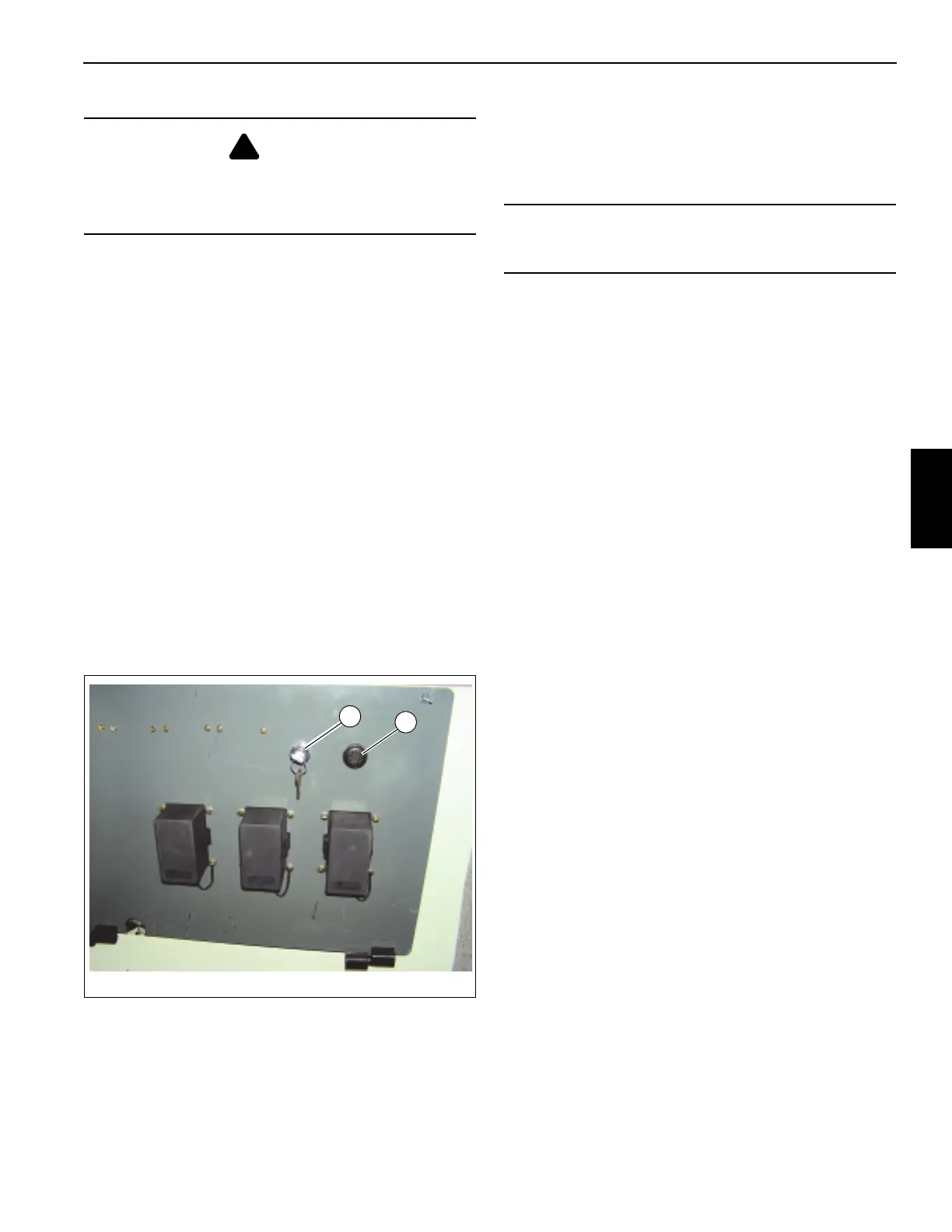
The RCL control can be turned completely off and back on
using the switch (1, Figure 3-5) located behind the cab seat.
Hydraulic Oil Indicator
The hydraulic oil temperature warning light (7, Figure 3-3) is
located on the crane cable console and illuminates when the
hydraulic oil overheats. If overheating occurs, run the crane
at idle with the controls in neutral until the light goes out.
Swing Brake Indicator
The swing brake indicator (8, Figure 3-3) is located on the
crane cab console. The indicator light is on when the swing
brake is activated.
Main Hoist Minimum Wrap Indicator
When the main hoist is down to the last cable wrap the
minimum wrap indicator (9, Figure 3-3) will flash intermittent
and the minimum wrap buzzer (2, Figure 3-5) will sound
intermittently.
When the amount of cable left on the hoist reaches the
minimum wrap; the indicator light will be constant, the buzzer
will be constant and the hoist will be disabled by the
minimum wrap sensor system.
Main Hoist Speed Switch
The main hoist speed selector switch (10, Figure 3-3) is
located on the right seat armrest. It is a three position switch
(on-off-on), placarded as rabbit (fast) hoist motor speed and
turtle (slow) hoist motor speed.
Hand Throttle Control
The push/pull hand throttle (11, Figure 3-4) is located on the
crane cab console and has the following functions.
Increase Engine Speed - Push in and hold the center button
(1, Figure 3-6); pull out on the knob (2) to accelerate the
engine. Releasing button (1) will lock knob in place and
maintain engine speed.
Decrease Engine Speed - Push in and hold the center button
(1, Figure 3-6); push the knob (2) in to slow the engine
speed.
Incremental Speed Adjustment - Rotate knob (2, Figure 3-6)
clockwise to increase speed and counterclockwise to
decrease engine speed.
The hand throttle must be positioned as shown in Figure 3-6
to operate the foot throttle (4, Figure 3-4) properly.
DANGER
The RCL only aids the operator when properly
programmed with the proper load chart and crane
configuration. To prevent injury or death to personnel, be
sure the RCL is programmed before crane operation.
NOTICE
Do not operate the crane with overheated hydraulic oil or
damage to seals in the hydraulic components may result.

 Loading...


