4-2 Published 4-23-2018 Control # 239-11
SET-UP NBT40 SERIES OPERATOR MANUAL
11. Always put spring clips in pins to ensure that they will
stay in place.
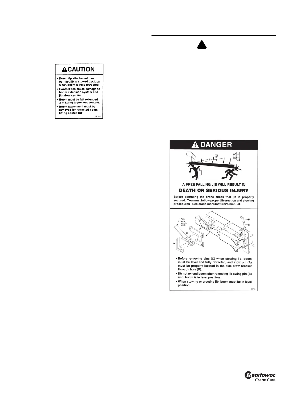
12. When the jib is stowed, the boom can not be fully
retracted if a boom tip attachment option is installed.
Also, on manually extendable jib options:
1. Extension retaining pin (E) must always be installed
when operating.
2. All swing around (stow and unstowing) operations shall
be done with jib retracted and pinned.
3. Extendable section may slide out of 1
st
section jib when
pin (E) is removed. Keep personnel clear of area.
JIB OPERATION
Deployment Procedure
1. Using boom telescope function, fully retract boom.
2. Using lift function, lower boom so that jib deployment
pins (C1, Figure 4-1) and (C2, Figure 4-1) are easily
accessible from the ground.
NOTE: When lowering the boom below horizontal, two
persons may be required. With the telescope
control in neutral, the boom may creep out when
below horizontal.
3. Install pins (C1, Figure 4-1) in upper and lower jib ears
secure with retainer spring clips. These pins are used as
a pivot point to swing jib into the deployed position.
4. Locate the stowed position of pins (C2, Figure 4-1). If in
jib attachment holes or boom sheave case jib holes,
remove pins from storage location.
5. Remove jib swing Pin (B, Figure 4-1) from top ear of jib.
6. Remove stow Pin (A, Figure 4-1) and stow in hook
bracket (D), secure with spring clip.
7. Attach tag line to sheave case end of jib.
8. Using the lift function, raise the boom to the horizontal
position.
9. Using telescope function, slowly extend boom
approximately one foot. This procedure will pull the jib
out of the jib stow bracket (H,Figure 4-1).
.
10. Using tag line, swing jib into deployed position.
11. Remove cable keeper pins from boom sheave case and
jib. Remove hook block. Pivot jib slightly to allow for
loadline to be removed from boom sheave case.
Remove loadline from boom sheave case and place in
an area to minimize possible damage.
12. Pivot jib into place, visually aligning the upper (C2,
Figure 4-1) pin holes. Install upper (C2) pin and spring
clip. A slight hammer strike may be necessary to install
pins. Always use proper eye protection during this step.
13. Use the jib jack (F, Figure 4-1) to align lower (C2) pin.
a. Remove the jack handle (G, Figure 4-1) from the
boom stowage bracket and check that the jack
release valve is closed.
b. Extend the jack (F, Figure 4-1) so that the lower (C2)
pin holes are aligned.
c. Install the lower (C2, Figure 4-1) pin and spring clip.
CAUTION
Use caution during this step. The jib is free to swing away
from the boom upon boom extension.

 Loading...


