National Crane Published 4-23-2018 Control # 239-11 3-9
NBT40 SERIES OPERATOR MANUAL OPERATING CONTROLS & PROCEDURES
Boom Lift Control Lever
The boom lift control lever (29, Figure 3-4) is located on the
right armrest and is used to raise and lower the boom. Push
the lever forward to lower the boom and pull back to raise the
boom.
Hoist Control Lever
The hoist control lever (30, Figure 3-4) is located on the right
armrest. Push forward to lower the load and pull the lever
back to raise the load.
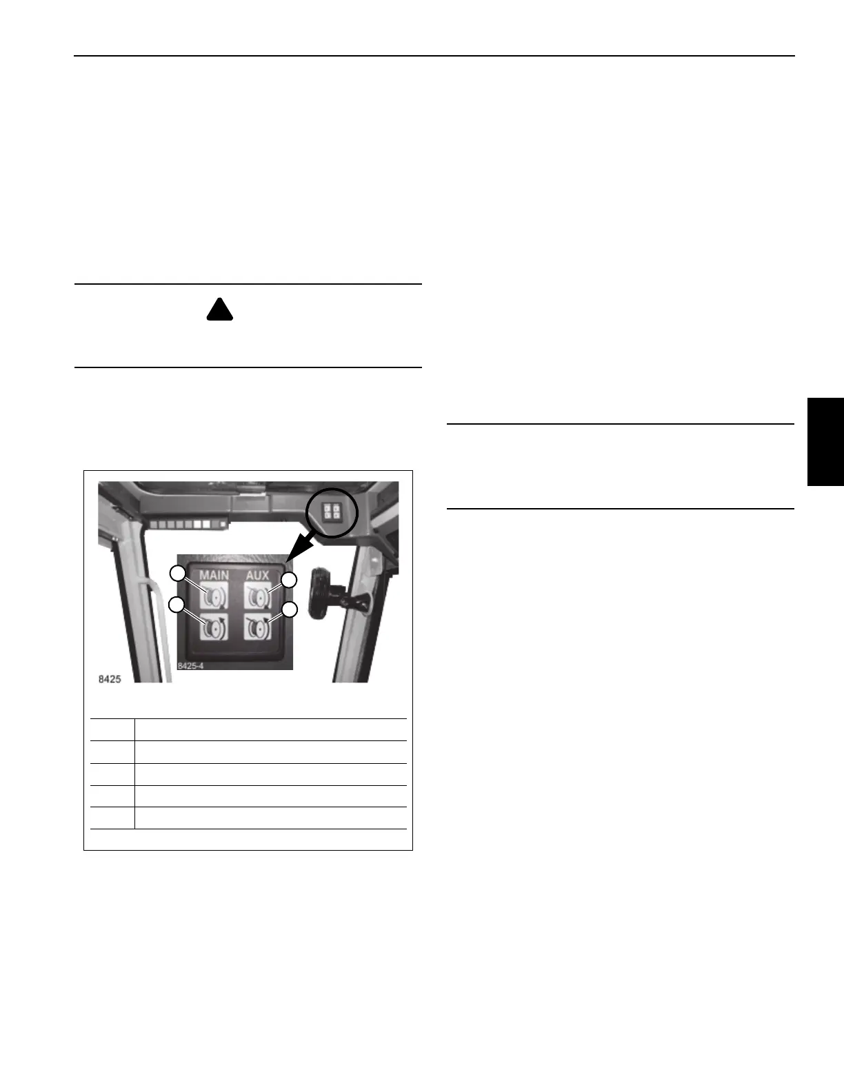
Hoist Rotation Indicator Display
The display is located in the front overhead panel Figure 3-7.
The LED display illuminates to indicate the current hoist in
operation and which direction the hoist is rotating.
Hoist Rotation Indicator
The hoist rotation indicator (RDI) is located on top of the
hoist control lever (30, Figure 3-3). The indicator is
electronically driven by a signal from an electronic
transmitter and sensor attached to the hoist. A pulsating
signal is sensed by the operator’s thumb during hoist
operation.
Telescope Control Lever
When equipped without the auxiliary hoist the telescope
boom control lever (31, Figure 3-4) is on the left armrest.
Push the lever forward to extend the boom and pull back to
retract the boom.
Auxiliary Hoist (Optional)
If equipped with an auxiliary hoist the control lever (31,
Figure 3-4) is on the left armrest, positioning the lever
forward lets out hoist cable. Pulling the lever back reels the
cable in.
Warning Horn Button
The warning horn button (32, Figure 3-4) is located on the
swing joy stick. Push the switch to sound the horn to warn
fellow workers of pending movement of crane.
Swing Control Lever
The swing control lever (33, Figure 3-4) is located on the left
armrest and controls turret rotation. Push the lever forward to
rotate the turret clockwise and pull back to rotate the turret
counterclockwise.
The swing control lever can be used to slow and stop the
swing by moving the control lever to the opposite direction of
the swing. For example, if the lever is pushed forward for a
clockwise swing, pull the lever back to slow and stop the
swing.
Seat Back Adjustment
To adjust the back of the seat press the adjustment knob (34,
Figure 3-4) and then adjust the seat as needed.
Seat & Seat Frame Lever
Moving the seat slide lever (35, Figure 3-4) will slide the seat
either forward or backward, moving the seat frame lever (36)
slides the seat and seat frame at the same time.
Climate Control Unit
Air Conditioner and Heating of the crane cab is provided by
the climate control unit (37, Figure 3-4) located under the
cab seat.
Swing Brake Switch
The swing brake switch (39, Figure 3-4) is located on the
crane cab console and is used to activate the swing brake
DANGER
Payout loadline before extending boom. Failure to do so
may cause the loadline to break or damage the crane.
FIGURE 3-7
8425-6
Item Description
1 Main Hoist UP (Clockwise)
2 Main Hoist DOWN (Counterclockwise)
3 Auxiliary Hoist UP (Clockwise)
4 Auxiliary Hoist DOWN (Counterclockwise)
1
2
3
4
CAUTION
Do not actuate the Swing Control Lever while the Swing
Brake is engaged, as the turret may push thro8ugh the
brake. Damage to the swing brake can occur.

 Loading...


