4-8 Published 4-23-2018 Control # 239-11
SET-UP NBT40 SERIES OPERATOR MANUAL
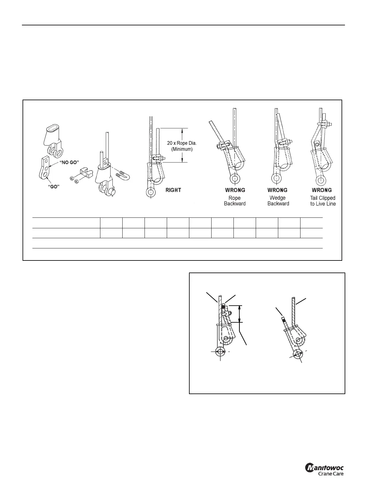
• If the wire rope passes through the “no go” hole, the
wedge is the wrong size.
• If the wire rope does not pass through the “go” hole,
the wedge is the wrong size.
2. Align the live end of rope, with center line of pin.
3. Secure dead end section of rope.
4. Tighten nuts on clip to recommended torque.
5. Do not attach dead end to live end or install wedge
backwards.
6. Use a hammer to seat Wedge and Rope as deep into
socket as possible before applying first load.
Wedge Socket Installation
1. Inspect the wedge and socket. Remove any rough
edges and burrs.
2. The end of the wire rope should be seized using soft, or
annealed wire or strand. If the end of the rope is welded,
the welded end should be cut off. Do not weld on size
6X37 rope. This will allow the distortion of the rope
strands, caused by the bend around the wedge, to
adjust themselves at the end of the line. Refer to
SECTION 1 - INTRODUCTION in the Service Manual
for wire rope procedures.
3. Make sure the live-end (Figure 4-6) of the rope is directly
in line with the ears of the socket and the direction of pull
to which the rope will be subjected. If the rope is loaded
into the socket incorrectly, under a load the rope will
bend as it leaves the socket, and the edge of the socket
will wear into the rope causing damage to the rope and
eventual failure.
.
4. Insert the end of the wire rope into the socket, form a
loop in the rope, and route the rope back through the
socket allowing the dead-end (Figure 4-6) to protrude
from the socket. Ensure the dead-end of the rope is of
sufficient length to apply end treatment to the dead-end
after the wedge has been seated.
FIGURE 4-5
Torque Value Table
Cable Size (inches) 3/8 7/16 1/2 9/16 5/8 3/4 7/8 1 1-1/8 1-1/4
Torque ft/lbs 45 65 65 95 95 130 225 225 225 360
Torque values shown are based upon clean dry threads free of lubrication.
Terminator Wedge Socket
Dead
End
Dead
End
Live End is
Entering
Wrong Side
Live
End
20 x Cable Dia
Minimum
RIGHT
WRONG
FIGURE 4-6
Wedge Socket

 Loading...


