National Crane Published 4-23-2018 Control # 239-11 3-15
NBT40 SERIES OPERATOR MANUAL OPERATING CONTROLS & PROCEDURES
Extension/Retraction Switch to EXTEND. The
appropriate stabilizer begins to move.
Extend each jack, positioning the float as necessary,
until the locking levers of the float engage the jack
cylinder barrel.
NOTE: More than one stabilizer can be extended at a time.
4. With each jack float firmly touching the ground, extend
the front stabilizers approximately 3 to 4 in (8 to 10 cm).
Extend the rear stabilizers approximately 3 to 4 in (8 to
10 cm).
5. Repeat step 4 until all wheels are clear of the ground
and the crane is level as indicated by the bubble level
indicator (Figure 3-13). If it is suspected that the bubble
level indicator is out of adjustment, verify and adjust the
bubble level using the procedures under Bubble Level
Adjustment, page 3-14.
6. Lower the center front stabilizer (optional) only after all
other outriggers are set. Press the front stabilizer switch
to activate and the extend/retract switch to extend. Hold
the extend/retract switch for two seconds after the
stabilizer contacts the ground. The front stabilizer is
automatically set at the correct ground pressure.
Outrigger Monitoring System (OMS)
(Optional—Standard in North America)
The Outrigger Monitoring System (OMS) aids the operator in
accurately programming the Rated Capacity Limiter (RCL)
by automatically identifying the position of each outrigger
beam. The OMS uses four sensors, one per outrigger beam,
to identify when an outrigger beam is positioned to one of
three pre-defined locations, including fully retracted, mid-
extend, and fully extended.
Set up of the outriggers is the same for cranes equipped with
OMS; refer to “Setting the Outriggers” on page 2-14.
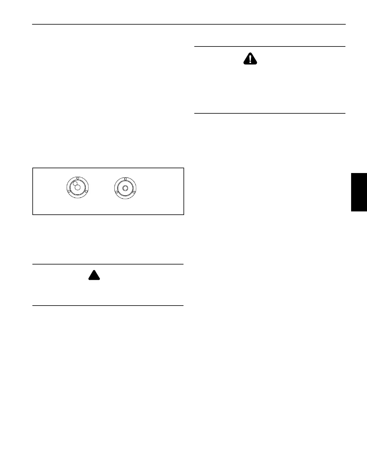
On cranes with OMS the symbols for the outriggers will
display on the crane’s remote control LCD Display screen
and also on the RCL screen (if equipped), refer to Figure 3-
14.
If the crane is setup on outriggers and “On Outriggers” is
chosen when programming the RCL, then the OMS indicates
to the RCL the horizontal position of each of the four
outrigger beams. Based on this information, the RCL will
default to the most conservative outrigger beam
configuration (i.e. If three outriggers are fully extended and
one is retracted, the RCL will select retracted as the
outrigger configuration). A confirmation of this configuration
is all that is needed (see Figure 3-14). Refer to the Rated
Capacity Limiter Operator’s Manual for detailed instructions.
DANGER
After the center front stabilizer is set, it automatically
retracts if any other jack is adjusted. Reset the center front
stabilizer if this occurs.
WARNING
Tipping Hazard!
The mid-extend outrigger beam lock pin must be engaged
before operating on any beam from the mid-extend
position.
The proper load chart and RCL program must be selected
for the current outrigger configuration.

 Loading...


