2-9
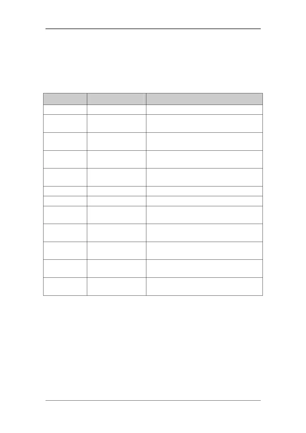
2.3.3 Main Board Interfaces
The main board implements connection and communication with other parts and peripheral
devices. The interfaces located on the main board are listed below:
No. Description What to connect
J1 LCD connector LCD screen
J2 SpO
2
board connector
SpO
2
board, providing power supply and
communicating the SpO
2
board
J3 SpO
2
sensor connector
SpO
2
board, connecting the SpO
2
sensor to the
SpO
2
board
J4
Multifunctional
connector
SpO
2
sensor or personal computer
J5
DSP simulator
connector
DSP simulator
J6 Speaker connector Speaker
J7 DC connector Charger stand
J8
Battery positive pole
connector
Battery positive pole
J9
Common earthing
connector
Charger stand or battery negative pole
J10 BC connector
Lithium-ion battery BC pole, detecting battery
type
J11 NTC connector
Lithium-ion battery NTC pole, detecting battery
temperature
J12
Power supply program
downloading connector
Power supply MCU programmer
 Loading...