3-6
A: AC mains (programmable and frequency adjustable)
B: Isolation transformer on the leakage current testing apparatus
C: Safety analyzer
D: Unit under test
Tools required:
Safety analyzer
Isolation transformer
3.5.1 Enclosure Leakage Current Test
1. Connect the 601 safety analyzer to an AC power supply (264 V, 60 Hz).
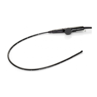
2. Connect the SpO
2
sensor to the RA terminal of the 601 safety analyzer.
3. Connect the pulse oximeter’s charger stand to the auxiliary power outlet of the 601
safety analyzer using a power cord.
4. Attach one end of the red lead to the “Red input terminal” of the analyzer, and the other
end to the tinsel over the enclosure of the EUT.
5. Power on the 601 safety analyzer and then press the “5-Enclosure leakage” button on the
analyzer’s panel to enter the enclosure leakage test screen.
6. Under normal condition, the enclosure leakage current should be no greater than 100 µA.
Under single fault condition, it should be no greater than 300 µA.
3.5.2 Patient Leakage Current Test
1. Connect the 601 safety analyzer to an AC power supply (264 V, 60 Hz).
2. Connect the SpO
2
sensor to the RA terminal of the 601 safety analyzer.
3. Connect the pulse oximeter under test to the auxiliary power outlet of the 601 safety
analyzer using a power cord.
4. Power on the 601 safety analyzer and then press the “6-Patient leakage” button on the
analyzer’s panel to enter the Patient leakage test screen.
5. Repeatedly press the “Applied Part” button to measure AC and DC leakage alternatively.
DC leakage reading is following by “DC”.
6. Under normal status, the patient leakage current should be no greater than 10 µA. Under
single fault condition, it should be no greater than 50 µA.
 Loading...