EasyManua.ls Logo

Mindray Zeus8 User Manual

Mindray Zeus8
292 pages
To Next Page IconTo Next Page
To Previous Page IconTo Previous Page
Page #12 background imageLoading...
Page #12 background image
VII
Safety
This chapter describes important issues related to safety precautions, as well as the labels and icons on
the ultrasound machine.
Meaning of Signal Words
In this service manual, the signal words DANGER, WARNING, CAUTION and NOTE are
used regarding safety and other important instructions. The signal words and their meanings are defined
as follows. Please understand their meanings clearly before reading this manual.
Signal word Description
DANGER
Indicates an imminently hazardous situation that, if not avoided, will result in
death or serious injury.
WARNING
Indicates a potentially hazardous situation that, if not avoided, could result in
death or serious injury.
CAUTION
Indicates a potentially hazardous situation that, if not avoided, may result in
minor or moderate injury.
NOTE Indicates a potentially hazardous situation that, if not avoided, may result in property
damage.
Description Important information that helps you use the system more effectively.
Symbols
The following tables provide location and information of the safety symbols and warning labels, please
read carefully.
Symbol Description Position
Type-BF applied part
The ultrasound transducers connected to this system
are type-BF applied parts.
The ECG module connected to this system is Type-
BF applied part.
On the right of the main unit
"Attention" indicates the points that you should pay
attention to. Be sure to read the Operators Manual
concerning these points before using the system.
Main unit

Table of Contents

Question and Answer IconNeed help?

Do you have a question about the Mindray Zeus8 and is the answer not in the manual?

Mindray Zeus8 Specifications

General IconGeneral
TypeAnesthesia Workstation
Ventilation ModesSIMV
Gas SupplyO2, Air, N2O
Transducer Frequency RangeNot applicable (Anesthesia Workstation)
Imaging ModesNot applicable (Anesthesia Workstation)
Power Supply100-240 VAC, 50/60 Hz
PortsUSB, Ethernet

Summary

Revision History

Intellectual Property Statement

Statement

Warranty Statements

Customer Service Department

Conventions

Safety

Meaning of Signal Words

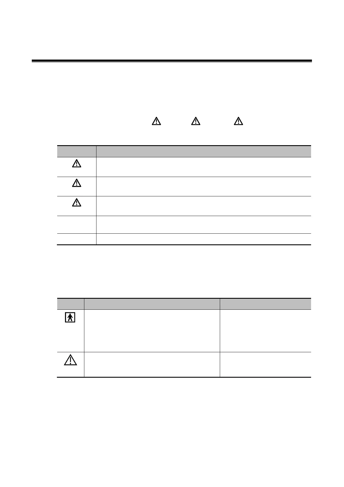
Defines signal words (DANGER, WARNING, CAUTION, NOTE) and their meanings for safety instructions.

Symbols

Provides information and location of safety symbols and warning labels used in the manual.

Warning Labels

Safety Precautions

Electric Safety

Mechanical Safety

Personnel Safety

Part I Service Scenarios

1 Installation

Details the procedures and requirements for installing the ultrasound system.

1.2 Installation

1.2.2 Transporting the Main Unit

Provides guidelines for safely transporting the main ultrasound unit and trolley.

1.2.4 Equipment Adjustment

1.2.5 Connecting Peripherals

1.2.6 Software Setup

1.2.6.12 Connecting to the network

1.2.6.13 Connecting to DICOM/HL7

1.2.6.15 Setting User Permissions

1.2.6.16 Setting Installment

1.2.6.17 Setting Security Policies

1.2.6.18 Connecting MedTouch/MedSight

Maintenance

2.1 Maintenance

Covers general maintenance procedures, including tools and regular maintenance items.

2.1.3 Daily Maintenance

2.1.4 Disinfecting the Main Unit

Check

2.2.1 General Check

Details the general checklist for inspecting the ultrasound system's components.

2.2.4 Mechanical Safety Check

Software Maintenance

2.3.1 Viewing System Information

Explains how to view system configuration, software version, and hardware details.

2.3.4 Software Recovery

2.3.5 Self-Test

2.3.6 Exporting and Viewing Logs

2.3.7 Optional Software Functions

2.3.8 Manage Settings

2.3.9 Patient Data Management

2.3.10 Recycle Bin Management

Repair

3.1 System Diagnosis and Support

Covers system indicators and basic information for diagnosis and support.

3.1.3 Get Entire Device Started

3.1.4 Alarm and Exception Information

3.1.9 Error Code List

3.1.10 Self-Test

Troubleshooting

3.2.1 System Power-up Failure

Provides troubleshooting steps for issues related to system power-up failures.

3.2.3 Image Related Faults

3.2.4 Probe Identification Failure

3.2.5 Troubleshooting of Control Panel

3.2.6 Troubleshooting of LCD Display

Update

4.1 Upgrading the Operating System and Ultrasound Application Software

Covers obtaining and upgrading the system's operating and application software.

4.3 Upgrading Hardware Functions

4.4 Upgrading the Probe and Biopsy Bracket

Part II General Information

1 Product Specifications

Details the system's intended use, appearance, and supported peripherals.

1.2 Technical Specifications

Product Principle

2.1 General Structure of Hardware System

Provides a schematic diagram and overview of the ultrasound system's hardware components.

2.2 Main Board

2.3 Probe Board

2.6 Control Panel

2.7 Main Display Unit

2.8 Probe Expansion Board

2.9 ECG Module

2.10 Trolley Power Supply

2.11 Power-up Process of the Main Unit

Probe and Needle-guided Bracket

3.1 Probe

Lists available probes, their models, information, and remarks for selection.

3.2 Needle-guided Brackets

Field Replaceable Unit

4.1 Explosive View

Illustrates the main assemblies of the system in an exploded view.

4.2 Assembly Explosive View

4.2.3 Main Unit Assembly (C0)

4.2.4 Cable and Accessories (D0)

4.2.5 MT3 Mobile Trolley (E0)

4.2.6 MT3 Mobile Trolley Cable (F0)

4.2.7 MT2 Mobile Trolley (G0)

Structure and Assembly/Disassembly

5.1 System Structure

Describes the overall structure of the system, including main unit and trolley components.

5.2 Assembly/Disassembly of the Main Unit

5.3 Disassembling the Trolley

Function and Performance Check

6.2 Checking System Status

Details how to check the system's operating status and environment.

6.3 General Check

6.4 Function Check

6.5 Performance Test

Part III Appendix

1 Electrical Connection Diagram

Illustrates the internal electrical connections of the main unit and trolley.

2 Description of Self-Test Items

Details various self-test procedures for system components.

3 Electrical Safety Maintenance

Covers electrical safety tests and procedures for ensuring device safety.

4 Phantom Usage Illustration

Provides illustrations and details for using ultrasound phantoms KS107BD and KS107BG.

Related product manuals