Part II General Information
Product Principle 135
If AC power is disconnected in the shutdown state, the power management FPGA will turn
off 5VSTB output and retains only 3.3VSTB if a battery is present. The system is powered
up only after you press the power button.
If AC power is disconnected in the standby state, the battery, if available, provides 5VSTB
and 3.3VSTB for the system.
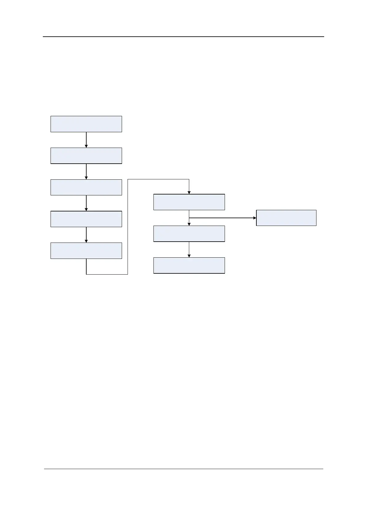
The following figure shows the power-up process.
Figure 2-15 System power-up process
Connect AC power
Press the power button (co nt ro l pa nel)
A valid PWR_BTN_N signal is received
(power management FPGA)
The pow er man age ment modu le tr ans mi ts
a valid PWRBTN# signal
S3# an d S4# invalid (sent by the COME
module)
DC-DC 1 2 V power-up
PWR_O K va li d (transmitted by the power
management module)
CPU startup (COME module)
The DC-DC board provides other
power supplies
2.11 Power-up Process of the Main Unit
The following figure shows the startup process of the main unit, and the power and display
conditions in different phases.
 Loading...


