22 | minnkotamotors.com
©2019 Johnson Outdoors Marine Electronics, Inc.
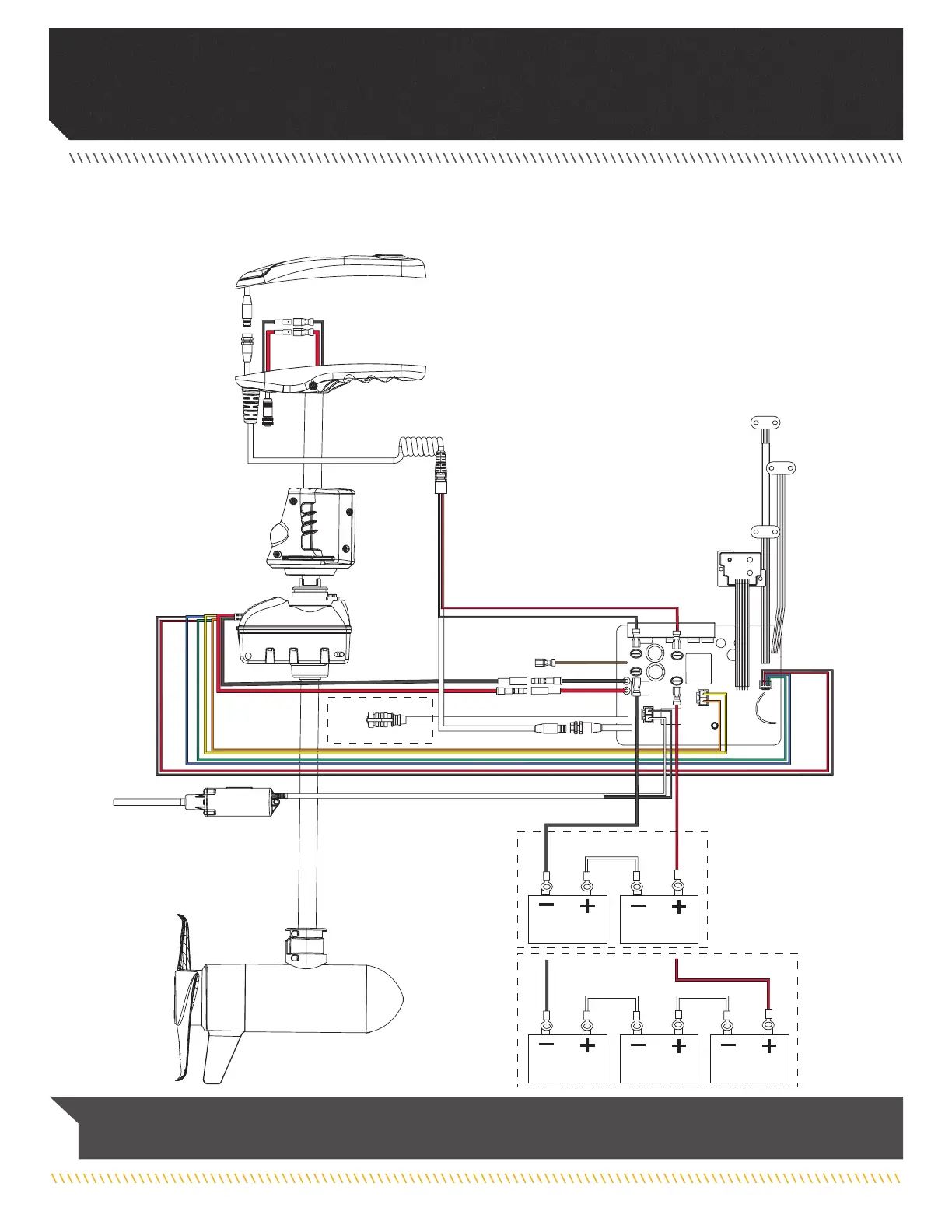
MOTOR WIRING DIaGRaM
Black M-
Black M-
Yellow
Orange
White
Black
Green
Red
Black
Red +
Red +
Black -
Black -
Red M+
Red M+
Control Head
Accessory
Attachment
Accessory Attachment
Foot Pedal
Brown
Coil Cord
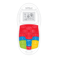
i-Pilot Link
Cable*
B-
M+
M-
B+
Red B+
Black B-
Blue
Trim
Housing
Steering
Housing
Attachment
24v*
36v*
Battery 1
Battery 2
Battery 1
Battery 2 Battery 3
Tilt Motor
Motor
Plunger
Sensor
Tilt
Sensor
Cam
Sensor
Indicator
Panel
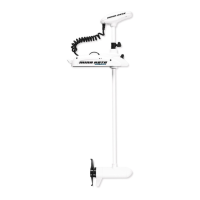
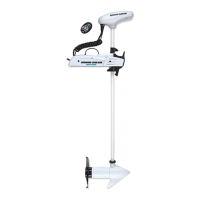
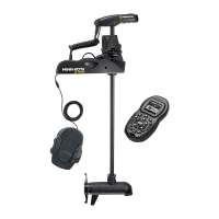
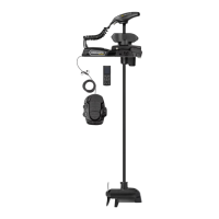
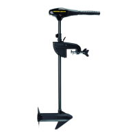
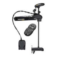
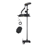
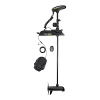
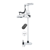
RIPTIDE ULTERRA WITH i-PILOT OR i-PILOT LINK
The following Motor Wiring Diagram applies to all Riptide Ulterra models that come factory installed with either i-Pilot or
i-Pilot Link.
NOTICE: This is a multi-voltage diagram. Double-check your motor's voltage for proper connections. Over-Current Protection
Devices are not shown in this illustration. *i-Pilot Link Cable attachment for i-Pilot Link only.
 Loading...