minnkotamotors.com | 43
©2019 Johnson Outdoors Marine Electronics, Inc.
ADvANCED TROUBLESHOOTING
CAUTION
Always wear safety glasses and gloves. Disconnect all power to the trolling motor before beginning any work or maintenance. Johnson
Outdoors Inc. is not responsible for any damage due to improper rigging or installation. If you do not have the skills, experience and
tools to perform the following maintenance and repairs, we recommend you seek the help of a Minn Kota Authorized Service Center.
A list of Authorized Service Centers can be found at minnkotamotors.com/support/service-providers/locate. Contact the Service
Department by email or, by dialing 800-227-6433.
1
2
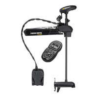
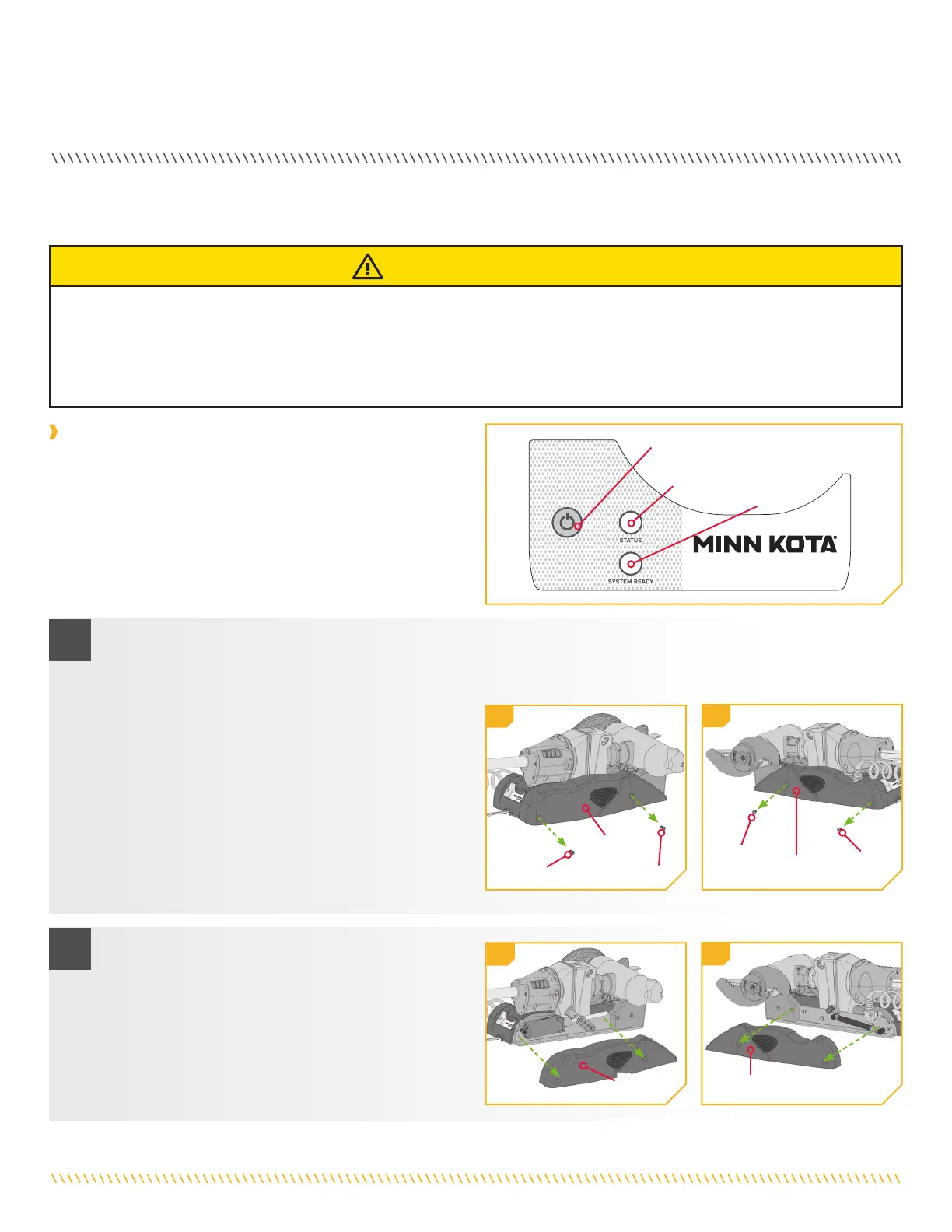
The Riptide Ulterra motor does not turn on when the Power button on
the control panel is pressed and released. The green “System Ready”
and red “Status” LEDS do not light up.
CAUSE: Inadequate voltage, reversed polarity, or the switch/LED
circuit board has come loose from the backside of the control panel.
a. Verify that the correct voltage is being supplied to the RT Ulterra motor (24-volts for RT Ulterra 80 and 36-volts for RT
Ulterra 112) and that polarity has not been inadvertently reversed. Refer to the Battery and Wiring Installation section of
this manual for additional details on wiring.
b. If no problems are found with the voltage and power
delivery/wiring system, then the Power switch/LED
circuit board may have come loose from the control
panel during shipment.
c. To check for this remove the ¼-20 x ½” Phillips
head screws that hold the motor side plates in place
with a #2 or #3 screwdriver. (two screws each in the
left and right side plates).
ADvANCED TROUBLESHOOTING
Left Sideplate
Right
Sideplate
Right
Sideplate
Screw
Screw
Left
Sideplate
Screw
Screw
1c
1c
2d
2d
d. With the side plates removed loosen the two small
10-32 x 3/8” Phillips head screws that hold the
control panel cover in place. Lift up the cover as
much as possible (due to the motor being stowed
there is not much room for this) and look along the
backside inner surface of the control panel cover to
see if the Power switch/LED display is in place.
Case 1
The following advanced scenarios may help you troubleshoot your Ulterra motor.
Status
Indicator
Power Button
System Ready
Indicator
CORRECTIVE ACTION:
 Loading...