6
Wiring
Detection (IDC) Zones
The system has six detection zones (three for the FA-103). Refer to Figure 7 on page 8 for wiring instruction
and to Table 1 on page 9 for wire size.
Signal (NAC) Zones
There are two signal zones available for bells and horns providing 1.25A maximum per zone with 2A maximum
total signal power. Refer to Figure 7 on page 8 for NAC circuit for wiring instruction and to Table 2 on page 9 for
wire size.
Alarm and Trouble Relays
Alarm and trouble relay contacts are provided. Refer to Figure 8 on page 10 for contact location and
designation.
Remote Annunciation
Annunciation outputs are provided for connection to an RTI-1 Remote Trouble indicator. Refer to Figure 8 on
page 10 for wiring instruction.
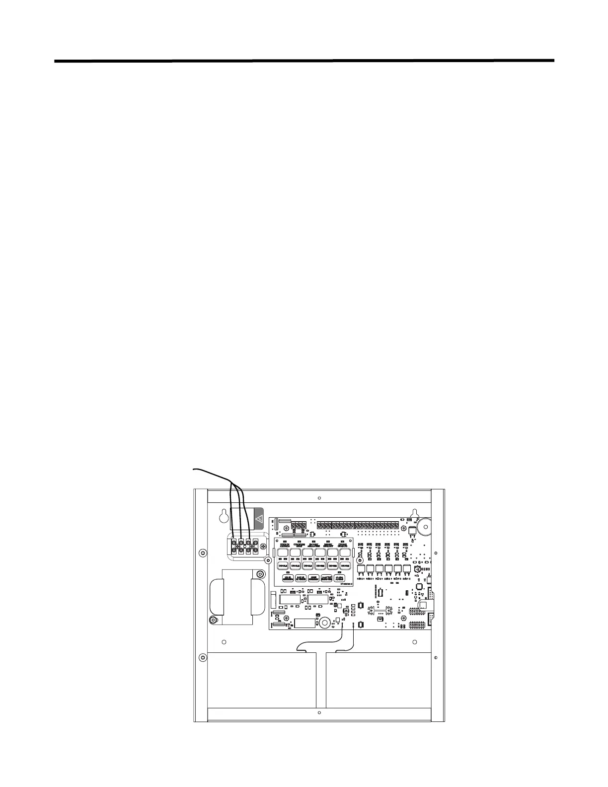
A.C. Power and Batteries
The A.C. power is connected to the terminal block above the transformer.
NOTE: SET DIP SW12 SWITCHES 7 AND 8 ACCORDING TO INPUT VOLTAGE USED, SEE PAGE 5.
Use Gel Cell or Sealed Lead-Acid type of batteries only. Connect the batteries after power up. For greater
accuracy, use the battery calculations chart located in Appendix C PAGE 16.
ELECTRICAL RATING: 120V, 60Hz, 1A / 240V, 50Hz, 0.5A
Figure 5: A.C. Power and Battery Connection
240VAC 50Hz
120VAC 60Hz
N
Ground
240VAC 50Hz
120VAC 60Hz
N
Ground
+
_
AC POWER
BATTERY BATTERY

 Loading...


