Wiring Tables and Information
10
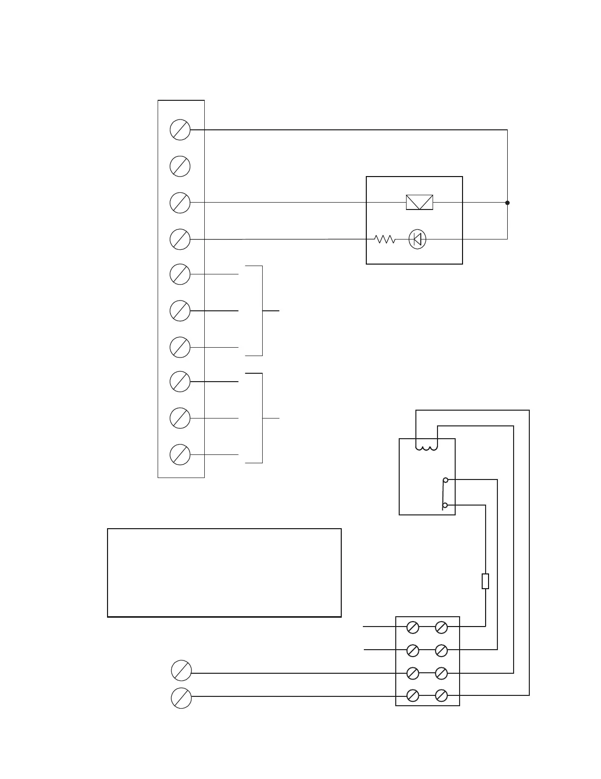
Figure 8: Alarm and trouble relay contacts, remote annunciation and four-wire
detector wiring instructions
Common Alarm
relay contacts
28VDC, 3A (resistive)
Common trouble
relay contacts
28VDC, 3A
(resistive)
N C
C
N O
N C
C
N O
TRL
TRB
24VDC, 16.5 mA max.
unsupervised
unsupervised
24VDC, 16.5 mA max.
1.5K
remote trouble
LED (amber)
remote trouble buzzer
24V (+) 24VDC, 250mA max. Resettable or Always ON
24V (+) 24VDC, 250mA max.
GND Not used
GND
ELR
3.9K
1/2 W
RTI-1
BLACK
BLUE
RED
WHITE
Resettable
Aux 24V DC
Resettable
Aux 24V DC
+
-
+
-
TO
DETECTION
ZONE
+
-
+
-
POWER
+
+
-
-
LAST 4-WIRE
DETECTION
DEVICE
END OF L INE RELAY
LI STED S3705
MODEL ELOR-1A
MANUFACTURED BY
SYS TEM SENSOR
4-WIRE DETECTOR APPLICATION
Connect Aux 24V DC either to a RTI-1 OR to
4-wire detection device. Cannot be both.
RTI-1 CONNECTION
4-WIRE DETECTOR WIRING
Red
Black
Violet
Violet
Contact
Normally
Closed
with power
Coil
Use ULC Listed 4 wire smoke detectors
nominally rated 24V.

 Loading...


