FA-106 Installation and Operation Manual
5
DIP SWITCH SELECTION
DIP switch SW12 is used to set the preferred signal zone outputs, the signal silence inhibit, the detection zone
operation and auxiliary functions. DIP switch SW12 is located in the bottom right corner of the main printed
circuit board, refer to Figure 6 on page 7.
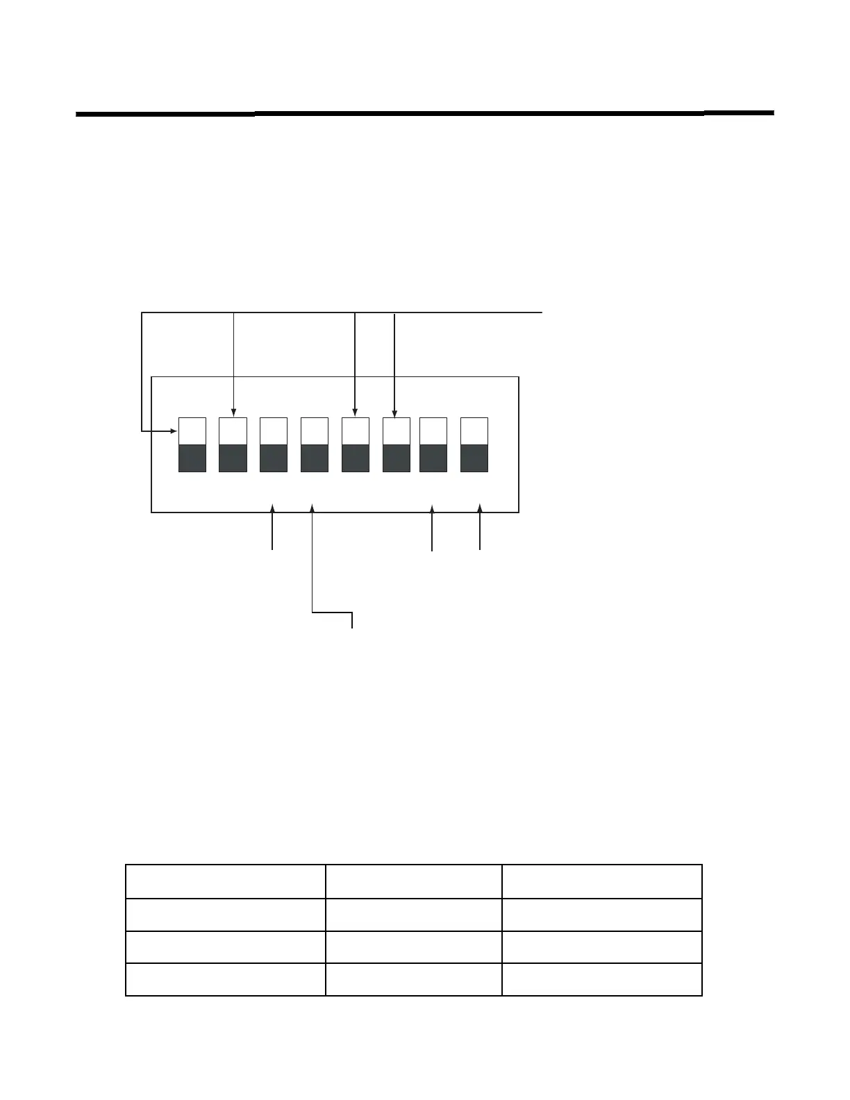
Figure 4: Setting the DIP Switch functions
• Temporal Code: 3 rounds of 0.5 second ON, 0.5 second OFF, then 1.5 second pause.
• Steady: Signal on continuously.
Set DIP SW12 switches 7 and 8 according to the input voltage which will be connected to the
fire alarm panel.
INPUTVOLTAGE DIPSWITCHSW12‐7DIPSWITCHSW12‐8
120V OFF OFF
240V ON OFF
220V OFF ON
1 2 3 4 5 6 7 8
ON
Alarm Relay
ON- Disconnects the Alarm Relay; panel will remain in trouble with
this switch in the ON position.
OFF- Alarm Relay always active during alarm (default)
Signal Silence
ON - 1 minute signal
silence inhibit
OFF - normal signal
silence (default)
DIP switch SW12
1 NAC Zone 1
ON - Steady
OFF - temporal code (default)
2 NAC Zone 2
ON - Steady
OFF - temporal code (default)
5 Aux 24V
ON- Resettable
OFF - Always 24V
6 Enable Zone Disconnect
ON - Disable (disconnect)
available per zone
OFF - Disable function not
available (default)
DIP switch 7 and 8 are set as per
input voltage used, see table below

 Loading...


