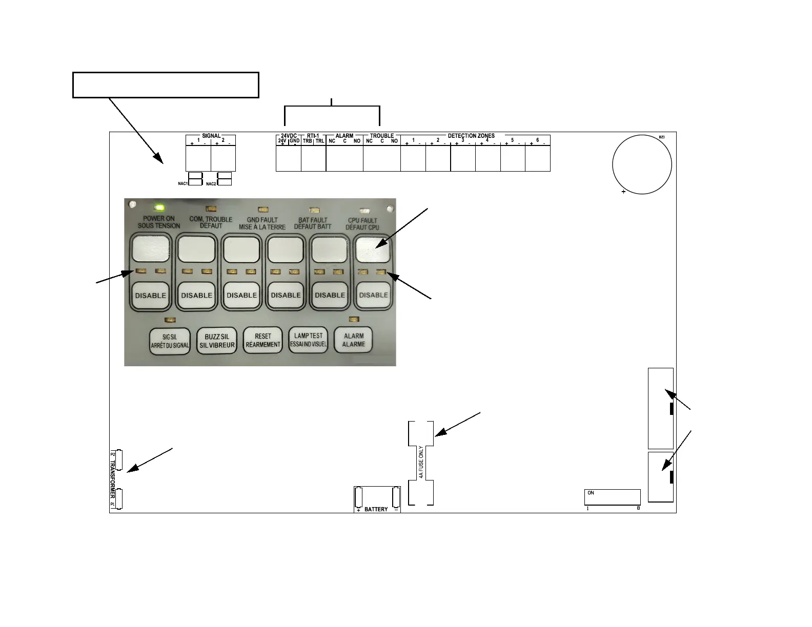
EasyManuals Logo
Home>Mircom>Control Panel>FA-103

Mircom FA-103 User Manual

Mircom FA-103
24 pages
To Next Page IconTo Next Page
To Previous Page IconTo Previous Page
Page #11 background imageLoading...
Page #11 background image
7
Figure 6: Circuit Board Layout
SW12
F2
P3
P4
Signal
Trouble
Active
Red
NAC CIRCUITS
1 AND 2
24V DC, RTI-1, ALARM AND RELAY TROUBLE CONTACTS
BATTERY
CONNECTION
+
-
For test
purposes
only
DETECTION ZONES 1 TO 6
DIP SWITCH SW12
ALARM
LED
per Zone
TROUBLE
LED
per Zone
Space for
Detection Zone
label
NAC active red LED and
NAC yellow trouble LED per NAC zone
The battery fuse protects against battery
It can be replaced with a 4A fast-acting
fuse with dimensions 1/4” x 1-1/4” ONLY.
shorts and reversals.
There is a non-field-replaceable fuse
in line with the transformer’s
secondary windings.

Questions and Answers:

Question and Answer IconNeed help?

Do you have a question about the Mircom FA-103 and is the answer not in the manual?

Mircom FA-103 Specifications

General IconGeneral
BrandMircom
ModelFA-103
CategoryControl Panel
LanguageEnglish

Related product manuals