Home
Mircom
Control Panel
FX-2000 series
Mircom FX-2000 series User Manual
4
of 1
of 1 rating
109 pages
Give review
Manual
Specs
To Next Page
To Next Page
To Previous Page
To Previous Page
Loading...
9
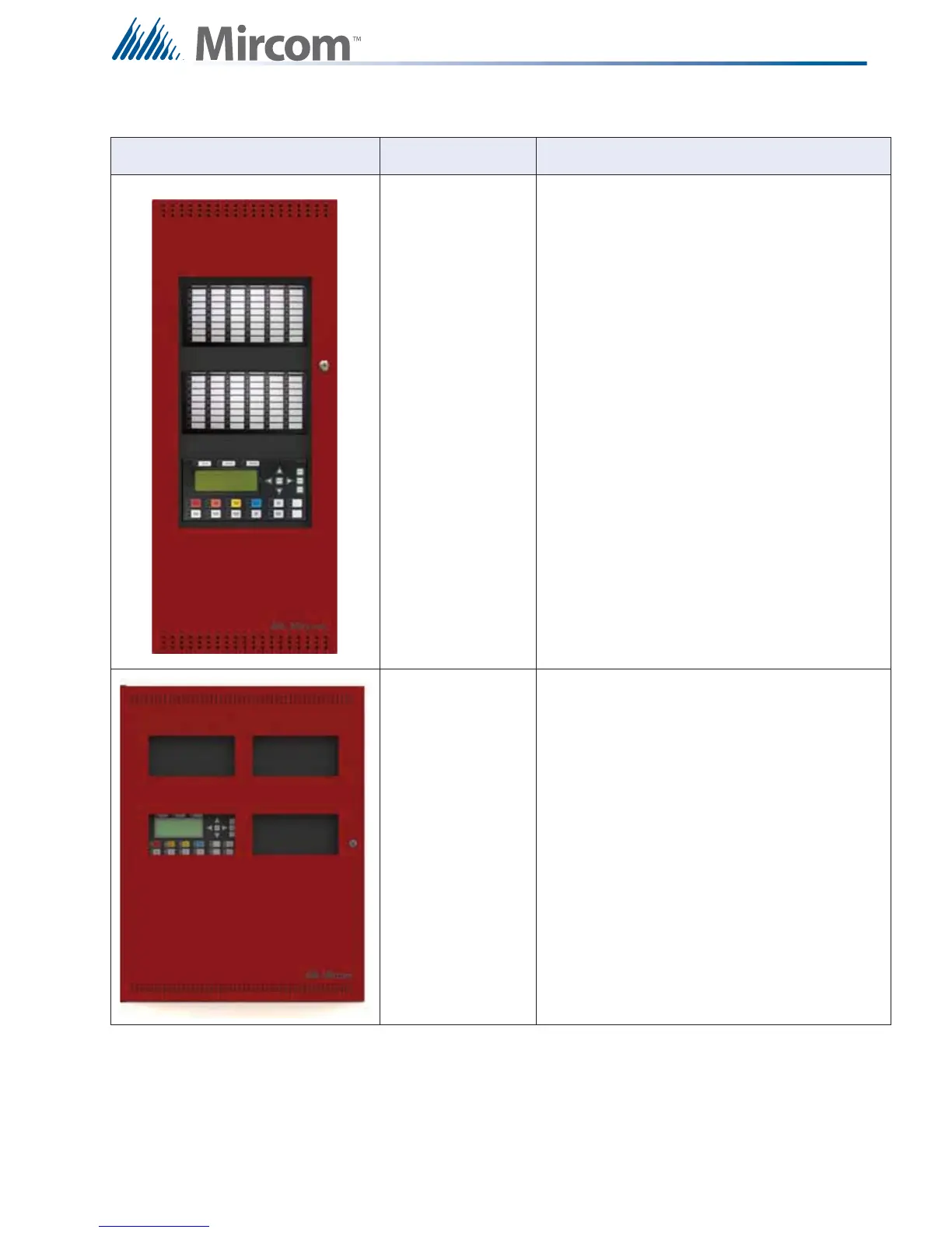
System Components
BBX-1024XT
BBX-1024XTR
Enclosure 35.5”H x 14.5”w x 5.25”D, white door
Enclosure 35.5”H
x 14.
5”w x 5.25”D, red door
BBX-1072ADS
BBX-1072ARDS
Enclosure
24.8” x 32.
5” x 6.4”, w
hite door
Enclosure
24.8” x 32.
5” x 6.4”, r
ed door
T
able 4 FX-2000
Enclosures
Model
Description
11
13
Table of Contents
Default Chapter
2
Table of Contents
2
1 Introduction
4
2 Document Conventions
6
3 System Components
7
4 Mechanical and Chassis Installation
15
5 Module Mounting Locations
26
6 Display and Adder Modules Mounting Locations
28
FX-2003-6DS/FX-2003-12DS/FX-2003-6DS-16LED Compact Main Chassis
28
FX-2017(S)-12DS MID-Size Main Chassis
28
FX-2009(S)-12DS Large Main Chassis
29
ECX-0012 Expander Chassis for FX-2009-12DS
29
7 Module Settings
32
Main Fire Alarm Modules (MD-764 Part of Main Chassis)
32
Main Fire Alarm Super Module (MD-757 Part of "S" Version Main Chassis)
33
RAX-1048TZDS Zone Display Module
35
IPS-2424DS Programmable Input Switches Module
35
Fan Damper Control Display Module (FDX-008W/WKI)
36
DM-1008A Hardwire Detection Adder Module
39
SGM-1004A Hardwire NAC Signal Adder Module
40
RM-1008A Hardwire Relay Adder Module
42
Polarity Reversal and City Tie Module (Model PR-300)
43
UDACT-300A Main Board
44
ALC-H16 Hardwire Loop Controller Module
50
8 Field Wiring
52
Main Fire Alarm Module Terminal Connections
52
Analog Loop Wiring
54
NAC Signal Module (SGM-1004A) Terminal Connections
61
UDACT-300A Main Board Terminal Connections
64
Wiring Tables and Information
66
9 System Checkout
68
10 Indicators and Controls
69
11 Operation
75
Single Stage Operation
75
Two Stage Operation
76
Pre-Signal Operation
77
UUKL Feature
77
Output Circuit Delay Operation
77
Circuit Types
78
12 Appendix A: Specifications
82
13 Appendix B: Compatible Devices
88
FX-2000 Series Compatible Addressable Loop Devices (UL)
88
FX-2000 Series Compatible Two-Wire Smoke Detectors (UL)
89
FX-2000 Series Compatible Four-Wire Smoke Detectors (UL Listed)
91
FX-2000 Series Compatible Signalling Devices (UL Listed)
91
FX-2000 Series Compatible Addressable Loop Devices (ULC)
92
FX-2000 Series Compatible Hardwire Smoke Detectors (ULC)
93
FX-2000 Series Compatible Synchronized Modules and Strobes
94
14 Appendix C: Power Supply and Battery Calculations
95
15 Appendix D: Remote Annunciator Panels
97
16 Appendix E: DIP Switch Settings Summary
99
17 Appendix F: Alarm Verification Timing
101
18 Appendix G: Wiring for Supervised Output Module
102
19 Appendix H: Label Requirements for Zone Identification
103
Other manuals for Mircom FX-2000 series
User Guide
36 pages
Operation
10 pages
4
Based on 1 rating
Ask a question
Give review
Questions and Answers:
Need help?
Do you have a question about the Mircom FX-2000 series and is the answer not in the manual?
Ask a question
Mircom FX-2000 series Specifications
General
Brand
Mircom
Model
FX-2000 series
Category
Control Panel
Language
English
Related product manuals
Mircom FX-2000
88 pages
Mircom FX-2003-6DS
109 pages
Mircom FX-2003-12DS
109 pages
Mircom FX-2003-6DS-16LED
109 pages
Mircom FX-2017-12ADS
109 pages
Mircom FX-400
84 pages
Mircom FX-401
91 pages
Mircom FX-351 SERIES
20 pages
Mircom FA-300-3DR
112 pages
Mircom FA-301-12LDR
106 pages
Mircom FA-200 Series
52 pages
Mircom FA-1000 SERIES
88 pages

 Loading...


