39
Module Settings
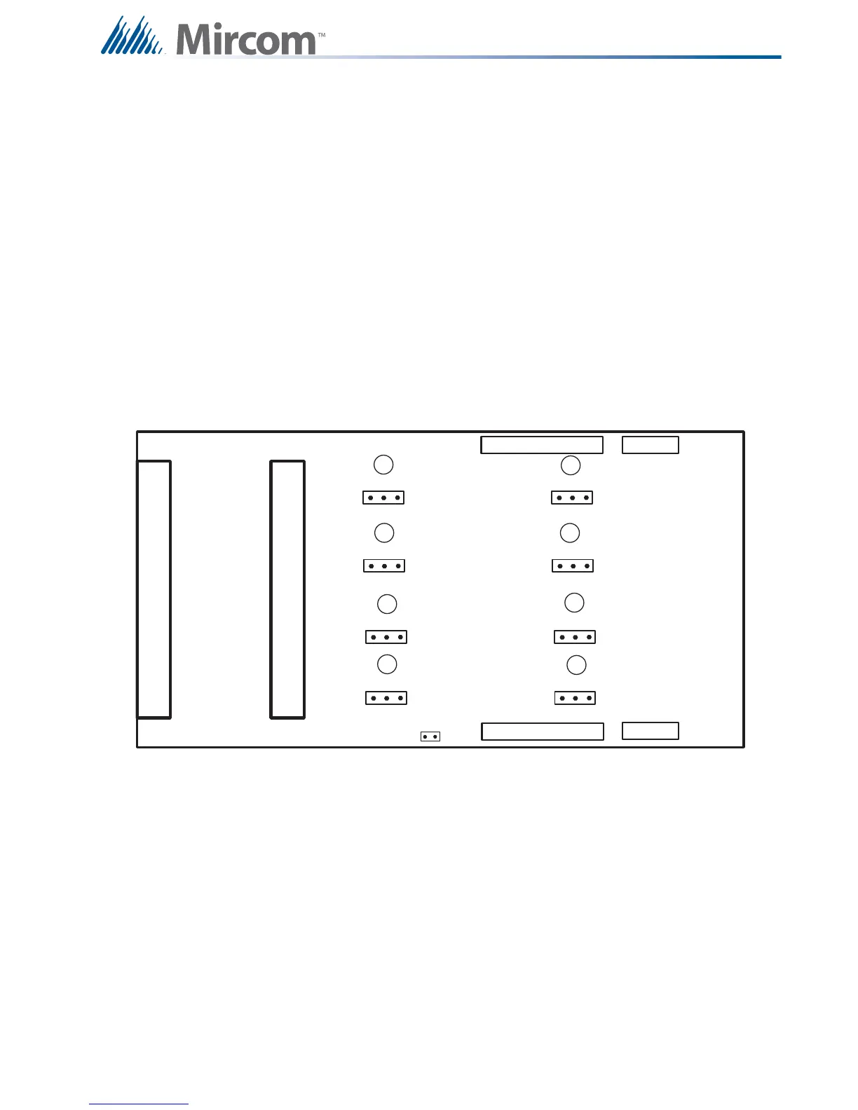
7.8 RM-1008A Hardwire Relay Adder Module
.
Figure 25 Hardwire Relay Adder Module (RM-1008A)
P2 Data cable to P6 or P5 of main fire alarm module, or to P12 or P13 of Hardwire
loop controller module, or to previous adder module.
P1 Data connector for next adder module.
P4 Power connector to P8 of main fire alarm module, or to P2 of Hardwire loop
controller or to previous adder module.
P3 Power connector for next adder module.
JW1 Remove continuity jumper if there are any more adder modules installed. If this
is the last module installed, leave JW1 on.
JP1-JP8 Move jumpers from pins 1 and 2 to 2 and 3 to connect relay commons between
two or more relays.
P1
P3
P4
FIELD WIRING TERMINALS
P2
JW1
FIELD WIRING TERMINALS
3 2 1
3 2 1
3 2 1
3 2 1
3 2 1
3 2 1
3 2 1
3 2 1
JP1
JP2
JP3
JP4
JP5
JP6
JP7
JP8
I1
I2
I3
I4
I5
I6
I7
I8

 Loading...


